

Breaker Interface Module II - Eaton Canada
Breaker Interface Module II - Eaton Canada
Breaker Interface Module II - Eaton Canada

You also want an ePaper? Increase the reach of your titles
YUMPU automatically turns print PDFs into web optimized ePapers that Google loves.
I.B. 29C893B Page 19<br />
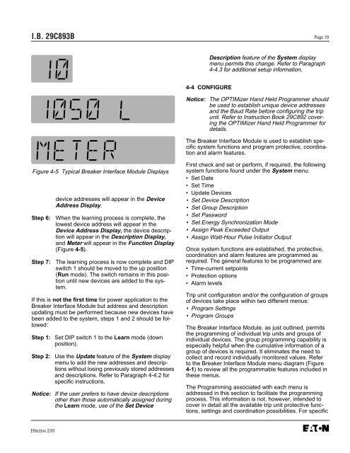
Figure 4-5 Typical <strong>Breaker</strong> <strong>Interface</strong> <strong>Module</strong> Displays<br />
Effective 2/01<br />
device addresses will appear in the Device<br />
Address Display.<br />
Step 6: When the learning process is complete, the<br />
lowest device address will appear in the<br />
Device Address Display, the device description<br />
will appear in the Description Display,<br />
and Meter will appear in the Function Display<br />
(Figure 4-5).<br />
Step 7: The learning process is now complete and DIP<br />
switch 1 should be moved to the up position<br />
(Run mode). The switch remains in this position<br />
until new devices are added to the system.<br />
If this is not the first time for power application to the<br />
<strong>Breaker</strong> <strong>Interface</strong> <strong>Module</strong> but address and description<br />
updating must be performed because new devices have<br />
been added to the system, steps 1 and 2 should be followed:<br />
Step 1: Set DIP switch 1 to the Learn mode (down<br />
position).<br />
Step 2: Use the Update feature of the System display<br />
menu to add the new addresses and descriptions<br />
without losing previously stored addresses<br />
and descriptions. Refer to Paragraph 4-4.2 for<br />
specific instructions.<br />
Notice: If the user prefers to have device descriptions<br />
other than those automatically assigned during<br />
the Learn mode, use of the Set Device<br />
Description feature of the System display<br />
menu permits this change. Refer to Paragraph<br />
4-4.3 for additional setup information.<br />
4-4 CONFIGURE<br />
Notice: The OPTIMizer Hand Held Programmer should<br />
be used to establish unique device addresses<br />
and the Baud Rate before configuring the trip<br />
unit. Refer to Instruction Book 29C892 covering<br />
the OPTIMizer Hand Held Programmer for<br />
details.<br />
The <strong>Breaker</strong> <strong>Interface</strong> <strong>Module</strong> is used to establish specific<br />
system functions and program protective, coordination<br />
and alarm features.<br />
First check and set or perform, if required, the following<br />
system functions found under the System menu:<br />
• Set Date<br />
• Set Time<br />
• Update Devices<br />
• Set Device Description<br />
• Set Group Description<br />
• Set Password<br />
• Set Energy Synchronization Mode<br />
• Assign Peak Exceeded Output<br />
• Assign Watt-Hour Pulse Initiator Output<br />
Once system functions are established, the protective,<br />
coordination and alarm features are programmed as<br />
required. The general features to be programmed are:<br />
• Time-current setpoints<br />
• Protection options<br />
• Alarm levels<br />
Trip unit configuration and/or the configuration of groups<br />
of devices take place within two different menus:<br />
• Program Settings<br />
• Program Groups<br />
The <strong>Breaker</strong> <strong>Interface</strong> <strong>Module</strong>, as just outlined, permits<br />
the programming of individual trip units and groups of<br />
individual devices. The group programming capability is<br />
especially helpful when the cumulative information of a<br />
group of devices is required. It eliminates the need to<br />
collect and record individually monitored values. Refer<br />
to the <strong>Breaker</strong> <strong>Interface</strong> <strong>Module</strong> menu diagram (Figure<br />
4-1) to review all the programmable features included in<br />
these menus.<br />
The Programming associated with each menu is<br />
addressed in this section to facilitate the programming<br />
process. This information is not, however, intended to<br />
cover in detail all the available trip unit protective functions,<br />
settings and coordination possibilities. For specific


