

Breaker Interface Module II - Eaton Canada
Breaker Interface Module II - Eaton Canada
Breaker Interface Module II - Eaton Canada

Create successful ePaper yourself
Turn your PDF publications into a flip-book with our unique Google optimized e-Paper software.
Page 28<br />
Each simultaneous use of the same pushbuttons<br />
will clear the next alarm messages from<br />
memory. Clearing all the alarm messages<br />
would be indicated by the Alarm LED no<br />
longer being illuminated.<br />
Step 5: Use the Up or Down pushbuttons to access<br />
older stored “Alarm Messages.” They would also<br />
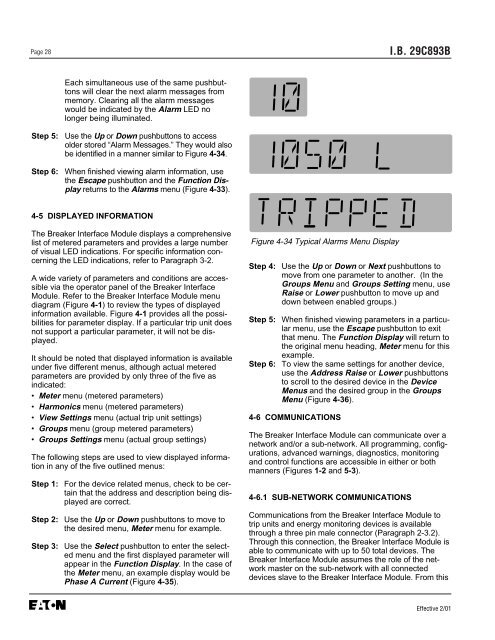
be identified in a manner similar to Figure 4-34.<br />
Step 6: When finished viewing alarm information, use<br />
the Escape pushbutton and the Function Display<br />
returns to the Alarms menu (Figure 4-33).<br />
4-5 DISPLAYED INFORMATION<br />
The <strong>Breaker</strong> <strong>Interface</strong> <strong>Module</strong> displays a comprehensive<br />
list of metered parameters and provides a large number<br />
of visual LED indications. For specific information concerning<br />
the LED indications, refer to Paragraph 3-2.<br />
A wide variety of parameters and conditions are accessible<br />
via the operator panel of the <strong>Breaker</strong> <strong>Interface</strong><br />
<strong>Module</strong>. Refer to the <strong>Breaker</strong> <strong>Interface</strong> <strong>Module</strong> menu<br />
diagram (Figure 4-1) to review the types of displayed<br />
information available. Figure 4-1 provides all the possibilities<br />
for parameter display. If a particular trip unit does<br />
not support a particular parameter, it will not be displayed.<br />
It should be noted that displayed information is available<br />
under five different menus, although actual metered<br />
parameters are provided by only three of the five as<br />
indicated:<br />
• Meter menu (metered parameters)<br />
• Harmonics menu (metered parameters)<br />
• View Settings menu (actual trip unit settings)<br />
• Groups menu (group metered parameters)<br />
• Groups Settings menu (actual group settings)<br />
The following steps are used to view displayed information<br />
in any of the five outlined menus:<br />
Step 1: For the device related menus, check to be certain<br />
that the address and description being displayed<br />
are correct.<br />
Step 2: Use the Up or Down pushbuttons to move to<br />
the desired menu, Meter menu for example.<br />
Step 3: Use the Select pushbutton to enter the selected<br />
menu and the first displayed parameter will<br />
appear in the Function Display. In the case of<br />
the Meter menu, an example display would be<br />
Phase A Current (Figure 4-35).<br />
Figure 4-34 Typical Alarms Menu Display<br />
I.B. 29C893B<br />
Step 4: Use the Up or Down or Next pushbuttons to<br />
move from one parameter to another. (In the<br />
Groups Menu and Groups Setting menu, use<br />
Raise or Lower pushbutton to move up and<br />
down between enabled groups.)<br />
Step 5: When finished viewing parameters in a particular<br />
menu, use the Escape pushbutton to exit<br />
that menu. The Function Display will return to<br />
the original menu heading, Meter menu for this<br />
example.<br />
Step 6: To view the same settings for another device,<br />
use the Address Raise or Lower pushbuttons<br />
to scroll to the desired device in the Device<br />
Menus and the desired group in the Groups<br />
Menu (Figure 4-36).<br />
4-6 COMMUNICATIONS<br />
The <strong>Breaker</strong> <strong>Interface</strong> <strong>Module</strong> can communicate over a<br />
network and/or a sub-network. All programming, configurations,<br />
advanced warnings, diagnostics, monitoring<br />
and control functions are accessible in either or both<br />
manners (Figures 1-2 and 5-3).<br />
4-6.1 SUB-NETWORK COMMUNICATIONS<br />
Communications from the <strong>Breaker</strong> <strong>Interface</strong> <strong>Module</strong> to<br />
trip units and energy monitoring devices is available<br />
through a three pin male connector (Paragraph 2-3.2).<br />
Through this connection, the <strong>Breaker</strong> <strong>Interface</strong> <strong>Module</strong> is<br />
able to communicate with up to 50 total devices. The<br />
<strong>Breaker</strong> <strong>Interface</strong> <strong>Module</strong> assumes the role of the network<br />
master on the sub-network with all connected<br />
devices slave to the <strong>Breaker</strong> <strong>Interface</strong> <strong>Module</strong>. From this<br />
Effective 2/01


