

Breaker Interface Module II - Eaton Canada
Breaker Interface Module II - Eaton Canada
Breaker Interface Module II - Eaton Canada

You also want an ePaper? Increase the reach of your titles
YUMPU automatically turns print PDFs into web optimized ePapers that Google loves.
I.B. 29C893B Page 9<br />
SECTION 3: OPERATOR PANEL<br />
3-1 GENERAL<br />
The operator panel, which is normally accessible from<br />
the outside of a panel or door, provides a means for<br />
being alerted to specific conditions, receiving functional<br />
help, programming, and parameter monitoring/selection<br />
(Figure 2-1). For the purpose of familiarization, the<br />
panel is divided into four sub-sections and discussed<br />
individually:<br />
• LEDs<br />
• Display Windows<br />
• Pushbuttons<br />
• Mimic Time-Current Curve<br />
NOTICE: I n and I r as used in any OPTIM Trip Unit<br />
System document are defined as follows:<br />
•I n = Rating Plug Value<br />
•I r = Long Delay Setting<br />
3-2 LEDS<br />
Eighteen LEDs are used to indicate a wide array of<br />
functions, operations and/or events. LEDs at the top of<br />
the <strong>Breaker</strong> <strong>Interface</strong> <strong>Module</strong> give a visual indication of<br />
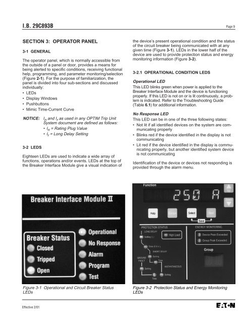
Figure 3-1 Operational and Circuit <strong>Breaker</strong> Status<br />
LEDs<br />
Effective 2/01<br />
the device’s present operational condition and the status<br />
of the circuit breaker being communicated with at any<br />
given time (Figure 3-1). LEDs in the lower half of the<br />
device are used to provide protection status and energy<br />
monitoring information (Figure 3-2).<br />
3-2.1 OPERATIONAL CONDITION LEDS<br />
Operational LED<br />
This LED blinks green when power is applied to the<br />
<strong>Breaker</strong> <strong>Interface</strong> <strong>Module</strong> and the device is functioning<br />
properly. If this LED is not on or is lit continuously, a problem<br />
is indicated. Refer to the Troubleshooting Guide<br />
(Table 6.1) for additional information.<br />
No Response LED<br />
This LED can be in one of the three following states:<br />
• Not lit if all identified devices on the system are communicating<br />
properly<br />
• Blinks red if the device identified in the display is not<br />
communicating<br />
• Lit red if the device identified in the display is communicating<br />
properly, but another identified system device<br />
is not communicating<br />
Identification of the device or devices not responding is<br />
provided through the alarm menu.<br />
Figure 3-2 Protection Status and Energy Monitoring<br />
LEDs


