

Breaker Interface Module II - Eaton Canada
Breaker Interface Module II - Eaton Canada
Breaker Interface Module II - Eaton Canada

Create successful ePaper yourself
Turn your PDF publications into a flip-book with our unique Google optimized e-Paper software.
I.B. 29C893B Page 33<br />
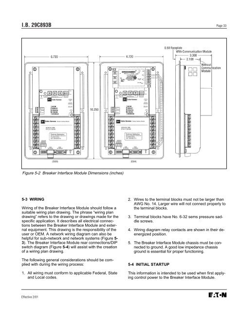
Figure 5-2 <strong>Breaker</strong> <strong>Interface</strong> <strong>Module</strong> Dimensions (inches)<br />
5-3 WIRING<br />
Wiring of the <strong>Breaker</strong> <strong>Interface</strong> <strong>Module</strong> should follow a<br />
suitable wiring plan drawing. The phrase “wiring plan<br />
drawing” refers to the drawing or drawings made for the<br />
specific application. It describes all electrical connections<br />
between the <strong>Breaker</strong> <strong>Interface</strong> <strong>Module</strong> and external<br />
equipment. This drawing is the responsibility of the<br />
user or OEM. A network wiring diagram can also be<br />
helpful for sub-network and network systems (Figure 5-<br />
3). The <strong>Breaker</strong> <strong>Interface</strong> <strong>Module</strong> rear connections/DIP<br />
switch diagram (Figure 5-4) will assist with the creation<br />
of a wiring plan drawing.<br />
The following general considerations should be complied<br />
with during the wiring process:<br />
1. All wiring must conform to applicable Federal, State<br />
and Local codes.<br />
Effective 2/01<br />
2. Wires to the terminal blocks must not be larger than<br />
AWG No. 14. Larger wire will not connect properly to<br />
the terminal blocks.<br />
3. Terminal blocks have No. 6-32 sems pressure saddle<br />
screws.<br />
4. Wiring diagram relay contacts are shown in their deenergized<br />
position.<br />
5. The <strong>Breaker</strong> <strong>Interface</strong> <strong>Module</strong> chassis must be connected<br />
to ground. A good low impedance chassis<br />
ground is essential for proper functioning.<br />
5-4 INITIAL STARTUP<br />
This information is intended to be used when first applying<br />
control power to the <strong>Breaker</strong> <strong>Interface</strong> <strong>Module</strong>.


