

Breaker Interface Module II - Eaton Canada
Breaker Interface Module II - Eaton Canada
Breaker Interface Module II - Eaton Canada

You also want an ePaper? Increase the reach of your titles
YUMPU automatically turns print PDFs into web optimized ePapers that Google loves.
Page 36<br />
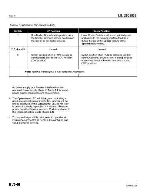
Table 5.1 Operational DIP Switch Settings<br />
ed power supply or a <strong>Breaker</strong> <strong>Interface</strong> <strong>Module</strong><br />
mounted power supply. Refer to Table 2.1 for exact<br />
power supply information and requirements.<br />
b. The Operational LED will blink green indicating a<br />
good operational status and Cutler-Hammer will be<br />
briefly displayed. If the Operational LED is not lit or<br />
is on continuously, a problem is indicated. Remove<br />
power from the <strong>Breaker</strong> <strong>Interface</strong> <strong>Module</strong> and refer to<br />
the Troubleshooting Guide (Table 6.1).<br />
c. To proceed beyond this point, refer to operational<br />
instructions presented in Section 4 to configure and<br />
setup particular devices.<br />
I.B. 29C893B<br />
Switch UP Position Down Position<br />
1 Run Mode - Normal switch position once Learn Mode - Switch position during initial power<br />
the <strong>Breaker</strong> <strong>Interface</strong> <strong>Module</strong> has learned application to the <strong>Breaker</strong> <strong>Interface</strong> <strong>Module</strong> or<br />
the identity of connected devices. during the use of the Update feature of the<br />
System display menu.<br />
2, 3, 4 and 5 Unused Unused<br />
6 Switch position when a PONI is used to Switch position when PONI is not being used for<br />
communicate over an IMPACC network. communications, or when PONI is being installed<br />
(“On” position) or removed from the <strong>Breaker</strong> <strong>Interface</strong> <strong>Module</strong>.<br />
(“Off” position)<br />
Note: Refer to Paragraph 2-3.1 for additional information.<br />
Effective 2/01


