

Breaker Interface Module II - Eaton Canada
Breaker Interface Module II - Eaton Canada
Breaker Interface Module II - Eaton Canada

Create successful ePaper yourself
Turn your PDF publications into a flip-book with our unique Google optimized e-Paper software.
I.B. 29C893B Page 31<br />
Effective 2/01<br />
button and Trip will be displayed (Figure<br />
4-39). For the OPTIM Trip Units a choice is<br />
now offered between a Trip or a Non-Trip<br />
test. The Magnum 1150 Trip Units can only<br />
perform a Non-Trip test.<br />
Step 6: Use the Up or Down pushbuttons to display<br />
the type of test desired, Trip or a Non-Trip.<br />
Step 7: Once Trip or a Non-Trip has been selected<br />
and is correctly displayed, use the Next pushbutton<br />
and the magnitude of the test current in<br />
amperes is displayed (Figure 4-40).<br />
Step 8: Use the Up or Down pushbuttons to arrive at<br />
the desired magnitude of test current.<br />
Step 9: Once the desired magnitude of test current is<br />
displayed, use the Select and Next pushbuttons<br />
simultaneously to activate the test. The<br />
test will be performed as programmed and the<br />
test time in seconds will be displayed (Figure<br />
4-41). Testing is now completed. It should be<br />
noted that the mimic time-current curve will<br />
appropriately indicate the test, the Alarm LED<br />
will be lit red, and the Cause of the Trip LED<br />
on the trip unit will be lit red.<br />
Step 10: Use the Escape pushbutton and Tripped will<br />
appear in the Function Display blinking<br />
(Figure 4-42). This indicates that alarm information<br />
is stored in memory for the test just<br />
concluded.<br />
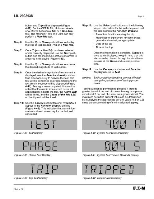
Figure 4-37 Test Display<br />
Figure 4-38 Phase Test Display<br />
Figure 4-39 Trip Test Display<br />
Step 11: Use the Select pushbutton and the following<br />
tripped information for the just completed test<br />
will scroll across the Function Display:<br />
• Protective function causing the trip<br />
• Magnitude of trip current for each phase,<br />
ground and neutral, as appropriate<br />
• Date of the trip<br />
• Time of the trip<br />
Once the information is complete, Tripped is<br />
once again displayed. Keep in mind that this<br />
alarm can be cleared through the simultaneous<br />
use of the Raise and Lower pushbuttons.<br />
Step 12: Use the Escape pushbutton and Function<br />
Display returns to Test.<br />
Notice: Basic protection functions are not affected<br />
during the performance of testing procedures.<br />
Testing will not be permitted to proceed if there is<br />
greater than 0.4 per unit of current flowing on a phase<br />
circuit or 0.2 per unit of current on a ground circuit. The<br />
maximum permitted current value can be determined<br />
by multiplying the appropriate per unit value (0.4 or 0.2)<br />
times the ampere rating of the installed rating plug.<br />
Figure 4-40 Typical Test Current Display<br />
Figure 4-41 Typical Test Time in Seconds Display<br />
Figure 4-42 Tripped Alarm Display


