Download the Plane Maker Manual - X-Plane
Download the Plane Maker Manual - X-Plane
Download the Plane Maker Manual - X-Plane

Create successful ePaper yourself
Turn your PDF publications into a flip-book with our unique Google optimized e-Paper software.
3.2. SHAPING THE FUSELAGE 13<br />
Parameter Positive value means... Negative value means...<br />
Heading offset Pivots to point right (starboard) Pivots to point left (port)<br />
Pitch offset Pivots to point up Pivots to point down<br />
Roll offset Rolls right (to starboard) Rolls left (to port)<br />
Table 3.2: Interpreting <strong>the</strong> direction-setting values<br />
2 to <strong>the</strong> number of sections you had in mind to account for <strong>the</strong> fuselage’s two closed ends. For<br />
instance, if, when looking at <strong>the</strong> body, you saw 13 “real” divisions, you would input 15 stations<br />
here: 13 “real” sections, which meet at a point at <strong>the</strong> nose and tail, for a total of 15.<br />
The “number of radii/side” value sets <strong>the</strong> number of points used in each half of <strong>the</strong> cross-section.<br />
Unless your aircraft has a very simple shape to its body, you’ll probably want to use <strong>the</strong> maximum<br />
of 9; this will allow <strong>the</strong> smoo<strong>the</strong>st curves possible on <strong>the</strong> body.<br />
The “body radius” setting controls <strong>the</strong> width of <strong>the</strong> cross-section views in <strong>the</strong> bottom half of<br />
<strong>the</strong> window. For <strong>the</strong> greatest accuracy when placing <strong>the</strong> points that make up <strong>the</strong> body, this should<br />
be set to <strong>the</strong> actual maximum radius of <strong>the</strong> fuselage. You should, however, err on <strong>the</strong> side of setting<br />
this too high so that all your points are visible.<br />
The final setting in <strong>the</strong> Body Data section of <strong>the</strong> window, labeled “body coeff of drag,” is <strong>the</strong><br />
body’s coefficient of drag based on its frontal area. This determines <strong>the</strong> amount of drag generated<br />
by <strong>the</strong> fuselage. An average fuselage will have a coefficient of drag of 0.1, while a very sleek one<br />
will have a coefficient of 0.025.<br />
The Body Location Box<br />
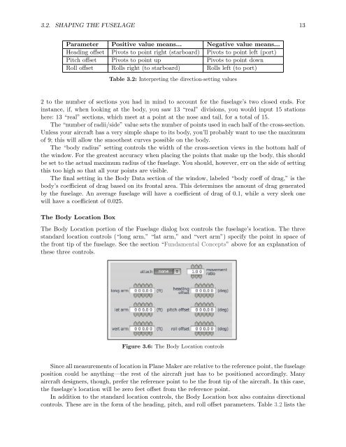
The Body Location portion of <strong>the</strong> Fuselage dialog box controls <strong>the</strong> fuselage’s location. The three<br />
standard location controls (“long arm,” “lat arm,” and “vert arm”) specify <strong>the</strong> point in space of<br />
<strong>the</strong> front tip of <strong>the</strong> fuselage. See <strong>the</strong> section “Fundamental Concepts” above for an explanation of<br />
<strong>the</strong>se three controls.<br />
Figure 3.6: The Body Location controls<br />
Since all measurements of location in <strong>Plane</strong> <strong>Maker</strong> are relative to <strong>the</strong> reference point, <strong>the</strong> fuselage<br />
position could be anything—<strong>the</strong> rest of <strong>the</strong> aircraft just has to be positioned accordingly. Many<br />
aircraft designers, though, prefer <strong>the</strong> reference point to be <strong>the</strong> front tip of <strong>the</strong> aircraft. In this case,<br />
<strong>the</strong> fuselage’s location will be zero feet offset from <strong>the</strong> reference point.<br />
In addition to <strong>the</strong> standard location controls, <strong>the</strong> Body Location box also contains directional<br />
controls. These are in <strong>the</strong> form of <strong>the</strong> heading, pitch, and roll offset parameters. Table 3.2 lists <strong>the</strong>