Download the Plane Maker Manual - X-Plane
Download the Plane Maker Manual - X-Plane
Download the Plane Maker Manual - X-Plane

You also want an ePaper? Increase the reach of your titles
YUMPU automatically turns print PDFs into web optimized ePapers that Google loves.
3.2. SHAPING THE FUSELAGE 15<br />
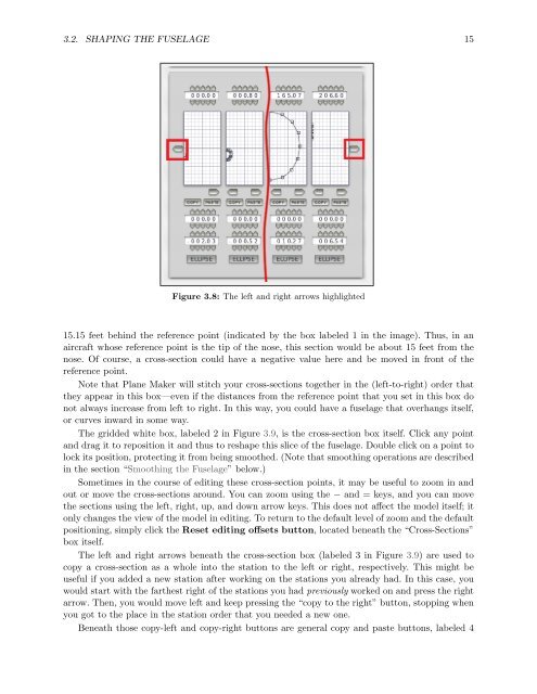
Figure 3.8: The left and right arrows highlighted<br />
15.15 feet behind <strong>the</strong> reference point (indicated by <strong>the</strong> box labeled 1 in <strong>the</strong> image). Thus, in an<br />
aircraft whose reference point is <strong>the</strong> tip of <strong>the</strong> nose, this section would be about 15 feet from <strong>the</strong><br />
nose. Of course, a cross-section could have a negative value here and be moved in front of <strong>the</strong><br />
reference point.<br />
Note that <strong>Plane</strong> <strong>Maker</strong> will stitch your cross-sections toge<strong>the</strong>r in <strong>the</strong> (left-to-right) order that<br />
<strong>the</strong>y appear in this box—even if <strong>the</strong> distances from <strong>the</strong> reference point that you set in this box do<br />
not always increase from left to right. In this way, you could have a fuselage that overhangs itself,<br />
or curves inward in some way.<br />
The gridded white box, labeled 2 in Figure 3.9, is <strong>the</strong> cross-section box itself. Click any point<br />
and drag it to reposition it and thus to reshape this slice of <strong>the</strong> fuselage. Double click on a point to<br />
lock its position, protecting it from being smoo<strong>the</strong>d. (Note that smoothing operations are described<br />
in <strong>the</strong> section “Smoothing <strong>the</strong> Fuselage” below.)<br />
Sometimes in <strong>the</strong> course of editing <strong>the</strong>se cross-section points, it may be useful to zoom in and<br />
out or move <strong>the</strong> cross-sections around. You can zoom using <strong>the</strong> − and = keys, and you can move<br />
<strong>the</strong> sections using <strong>the</strong> left, right, up, and down arrow keys. This does not affect <strong>the</strong> model itself; it<br />
only changes <strong>the</strong> view of <strong>the</strong> model in editing. To return to <strong>the</strong> default level of zoom and <strong>the</strong> default<br />
positioning, simply click <strong>the</strong> Reset editing offsets button, located beneath <strong>the</strong> “Cross-Sections”<br />
box itself.<br />
The left and right arrows beneath <strong>the</strong> cross-section box (labeled 3 in Figure 3.9) are used to<br />
copy a cross-section as a whole into <strong>the</strong> station to <strong>the</strong> left or right, respectively. This might be<br />
useful if you added a new station after working on <strong>the</strong> stations you already had. In this case, you<br />
would start with <strong>the</strong> far<strong>the</strong>st right of <strong>the</strong> stations you had previously worked on and press <strong>the</strong> right<br />
arrow. Then, you would move left and keep pressing <strong>the</strong> “copy to <strong>the</strong> right” button, stopping when<br />
you got to <strong>the</strong> place in <strong>the</strong> station order that you needed a new one.<br />
Beneath those copy-left and copy-right buttons are general copy and paste buttons, labeled 4