Download the Plane Maker Manual - X-Plane
Download the Plane Maker Manual - X-Plane
Download the Plane Maker Manual - X-Plane

You also want an ePaper? Increase the reach of your titles
YUMPU automatically turns print PDFs into web optimized ePapers that Google loves.
3.3. SHAPING THE WINGS 25<br />
detents below, as <strong>the</strong>y will be used in <strong>the</strong> maximum allowable flap deployment speeds. (Note that<br />
<strong>the</strong> max allowable speeds are set in <strong>the</strong> Viewpoint menu, as described in Chapter 4, in <strong>the</strong> section<br />
“Configuring Instrument Performance Ranges, Display Limits, and Colors”)<br />
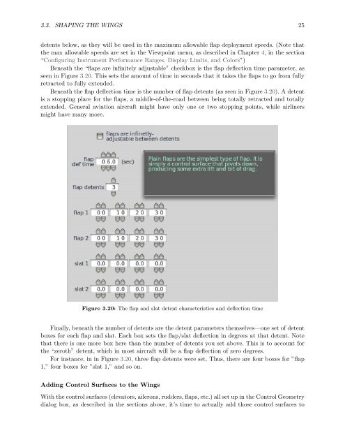
Beneath <strong>the</strong> “flaps are infinitely adjustable” checkbox is <strong>the</strong> flap deflection time parameter, as<br />
seen in Figure 3.20. This sets <strong>the</strong> amount of time in seconds that it takes <strong>the</strong> flaps to go from fully<br />
retracted to fully extended.<br />
Beneath <strong>the</strong> flap deflection time is <strong>the</strong> number of flap detents (as seen in Figure 3.20). A detent<br />
is a stopping place for <strong>the</strong> flaps, a middle-of-<strong>the</strong>-road between being totally retracted and totally<br />
extended. General aviation aircraft might have only one or two stopping points, while airliners<br />
might have many more.<br />
Figure 3.20: The flap and slat detent characteristics and deflection time<br />
Finally, beneath <strong>the</strong> number of detents are <strong>the</strong> detent parameters <strong>the</strong>mselves—one set of detent<br />
boxes for each flap and slat. Each box sets <strong>the</strong> flap/slat deflection in degrees at that detent. Note<br />
that <strong>the</strong>re is one more box here than <strong>the</strong> number of detents you set above. This is to account for<br />
<strong>the</strong> “zeroth” detent, which in most aircraft will be a flap deflection of zero degrees.<br />
For instance, in in Figure 3.20, three flap detents were set. Thus, <strong>the</strong>re are four boxes for ”flap<br />
1,” four boxes for ”slat 1,” and so on.<br />
Adding Control Surfaces to <strong>the</strong> Wings<br />
With <strong>the</strong> control surfaces (elevators, ailerons, rudders, flaps, etc.) all set up in <strong>the</strong> Control Geometry<br />
dialog box, as described in <strong>the</strong> sections above, it’s time to actually add those control surfaces to