Download the Plane Maker Manual - X-Plane
Download the Plane Maker Manual - X-Plane
Download the Plane Maker Manual - X-Plane

You also want an ePaper? Increase the reach of your titles
YUMPU automatically turns print PDFs into web optimized ePapers that Google loves.
3.3. SHAPING THE WINGS 27<br />
Check each of <strong>the</strong> boxes for <strong>the</strong> control surfaces that a wing section has. (Note once again that<br />
<strong>the</strong>se boxes will only actually do something to <strong>the</strong> wing if <strong>the</strong> control surfaces have been set up<br />
as described in <strong>the</strong> sections “Specifying Ailerons, Elevators, and O<strong>the</strong>r Surfaces” and “Specifying<br />
Flaps and Slats” above.)<br />
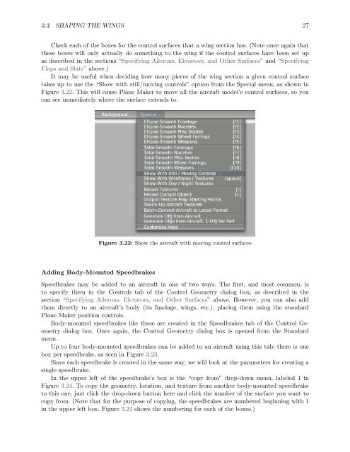
It may be useful when deciding how many pieces of <strong>the</strong> wing section a given control surface<br />
takes up to use <strong>the</strong> “Show with still/moving controls” option from <strong>the</strong> Special menu, as shown in<br />
Figure 3.22. This will cause <strong>Plane</strong> <strong>Maker</strong> to move all <strong>the</strong> aircraft model’s control surfaces, so you<br />
can see immediately where <strong>the</strong> surface extends to.<br />
Adding Body-Mounted Speedbrakes<br />
Figure 3.22: Show <strong>the</strong> aircraft with moving control surfaces<br />
Speedbrakes may be added to an aircraft in one of two ways. The first, and most common, is<br />
to specify <strong>the</strong>m in <strong>the</strong> Controls tab of <strong>the</strong> Control Geometry dialog box, as described in <strong>the</strong><br />
section “Specifying Ailerons, Elevators, and O<strong>the</strong>r Surfaces” above. However, you can also add<br />
<strong>the</strong>m directly to an aircraft’s body (its fuselage, wings, etc.), placing <strong>the</strong>m using <strong>the</strong> standard<br />
<strong>Plane</strong> <strong>Maker</strong> position controls.<br />
Body-mounted speedbrakes like <strong>the</strong>se are created in <strong>the</strong> Speedbrakes tab of <strong>the</strong> Control Geometry<br />
dialog box. Once again, <strong>the</strong> Control Geometry dialog box is opened from <strong>the</strong> Standard<br />
menu.<br />
Up to four body-mounted speedbrakes can be added to an aircraft using this tab; <strong>the</strong>re is one<br />
box per speedbrake, as seen in Figure 3.23.<br />
Since each speedbrake is created in <strong>the</strong> same way, we will look at <strong>the</strong> parameters for creating a<br />
single speedbrake.<br />
In <strong>the</strong> upper left of <strong>the</strong> speedbrake’s box is <strong>the</strong> “copy from” drop-down menu, labeled 1 in<br />
Figure 3.24. To copy <strong>the</strong> geometry, location, and texture from ano<strong>the</strong>r body-mounted speedbrake<br />
to this one, just click <strong>the</strong> drop-down button here and click <strong>the</strong> number of <strong>the</strong> surface you want to<br />
copy from. (Note that for <strong>the</strong> purpose of copying, <strong>the</strong> speedbrakes are numbered beginning with 1<br />
in <strong>the</strong> upper left box. Figure 3.23 shows <strong>the</strong> numbering for each of <strong>the</strong> boxes.)