5003 Lectures - Faculty of Engineering and Applied Science
5003 Lectures - Faculty of Engineering and Applied Science
5003 Lectures - Faculty of Engineering and Applied Science

You also want an ePaper? Increase the reach of your titles
YUMPU automatically turns print PDFs into web optimized ePapers that Google loves.
E<strong>5003</strong> - Ship Structures I 128<br />
© C.G. Daley<br />
" The method <strong>of</strong> moment distribution is this:<br />
1. Imagine all joints in the structure held so that they<br />
cannot rotate <strong>and</strong> compute the moments at the ends <strong>of</strong><br />
the members for this condition;<br />
2. At each joint distribute the unbalanced fixed-end<br />
moment among the connecting members in proportion to<br />
the constant for each member defined as "stiffness";<br />
3. Multiply the moment distributed to each member at a<br />
joint by the carry-over factor at the end <strong>of</strong> the member<br />
<strong>and</strong> set this product at the other end <strong>of</strong> the member;<br />
4. Distribute these moments just "carried over";<br />
5. Repeat the process until the moments to be carried over<br />
are small enough to be neglected; <strong>and</strong><br />
6. Add all moments - fixed-end moments, distributed<br />
moments, moments carried over - at each end <strong>of</strong> each<br />
member to obtain the true moment at the end."<br />
Description <strong>of</strong> Method<br />
The moment distribution method is a way to solve<br />
indeterminate structures comprised <strong>of</strong> beams. The<br />
method works for continuous beams over multiple<br />
supports <strong>and</strong> for frames. In its basic form it does<br />
not consider joint translation. All joints are only<br />
assumed to rotate, as would occur at a pin or roller<br />
support, or at a frame connection (beams to<br />
column) where sway is prevented. Subsidence <strong>of</strong> a<br />
support can easily be h<strong>and</strong>led. An extended<br />
version can treat sway <strong>of</strong> a frame system.<br />
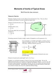
Fixed End Moments – FEM : To start the procedure,<br />
all joint are considered fixed <strong>and</strong> all fixed-end<br />
moments are calculated. One example <strong>of</strong> fixed end<br />
moments is shown below for a beam with a central<br />
point force. The moments are expressed as true<br />
moments acting on the supports. This is an<br />
important point. Note that both end moments in<br />
the sketch cause concave downward bending, <strong>and</strong><br />
would this have the same sign in a bending<br />
moment diagram. But here they have opposite<br />
true senses (clockwise on left <strong>and</strong> counterclockwise