
Create successful ePaper yourself
Turn your PDF publications into a flip-book with our unique Google optimized e-Paper software.
3 - PCI Card & Interfaces<br />
The MicroDock<br />
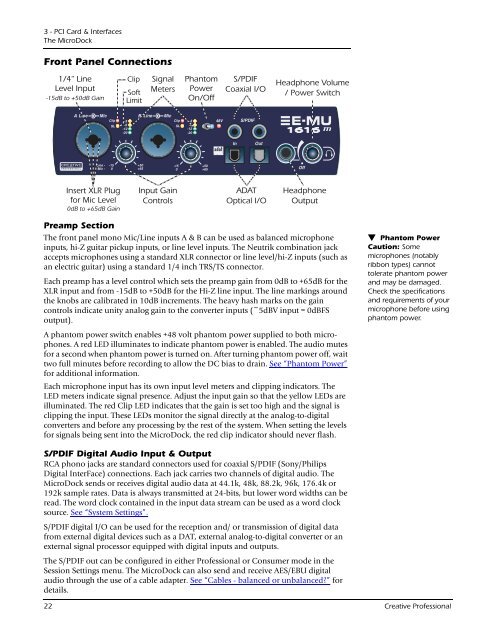
Front Panel Connections<br />
Preamp Section<br />
The front panel mono Mic/Line inputs A & B can be used as balanced microphone<br />
inputs, hi-Z guitar pickup inputs, or line level inputs. The Neutrik combination jack<br />
accepts microphones using a standard XLR connector or line level/hi-Z inputs (such as<br />
an electric guitar) using a standard 1/4 inch TRS/TS connector.<br />
Each preamp has a level control which sets the preamp gain from 0dB to +65dB for the<br />
XLR input and from -15dB to +50dB for the Hi-Z line input. The line markings around<br />
the knobs are calibrated in 10dB increments. The heavy hash marks on the gain<br />
controls indicate unity analog gain to the converter inputs (~5dBV input = 0dBFS<br />
output).<br />
A phantom power switch enables +48 volt phantom power supplied to both microphones.<br />
A red LED illuminates to indicate phantom power is enabled. The audio mutes<br />
for a second when phantom power is turned on. After turning phantom power off, wait<br />
two full minutes before recording to allow the DC bias to drain. See “Phantom Power”<br />
for additional information.<br />
Each microphone input has its own input level meters and clipping indicators. The<br />
LED meters indicate signal presence. Adjust the input gain so that the yellow LEDs are<br />
illuminated. The red Clip LED indicates that the gain is set too high and the signal is<br />
clipping the input. These LEDs monitor the signal directly at the analog-to-digital<br />
converters and before any processing by the rest of the system. When setting the levels<br />
for signals being sent into the MicroDock, the red clip indicator should never flash.<br />
S/PDIF Digital Audio <strong>Input</strong> & Output<br />
RCA phono jacks are standard connectors used for coaxial S/PDIF (Sony/Philips<br />
Digital InterFace) connections. Each jack carries two channels of digital audio. The<br />
MicroDock sends or receives digital audio data at 44.1k, 48k, 88.2k, 96k, 176.4k or<br />
192k sample rates. Data is always transmitted at 24-bits, but lower word widths can be<br />
read. The word clock contained in the input data stream can be used as a word clock<br />
source. See “System Settings”.<br />
S/PDIF digital I/O can be used for the reception and/ or transmission of digital data<br />
from external digital devices such as a DAT, external analog-to-digital converter or an<br />
external signal processor equipped with digital inputs and outputs.<br />
The S/PDIF out can be configured in either Professional or Consumer mode in the<br />
Session Settings menu. The MicroDock can also send and receive AES/EBU digital<br />
audio through the use of a cable adapter. See “Cables - balanced or unbalanced?” for<br />
details.<br />
Phantom Power<br />
Caution: Some<br />
microphones (notably<br />
ribbon types) cannot<br />
tolerate phantom power<br />
and may be damaged.<br />
Check the specifications<br />
and requirements of your<br />
microphone before using<br />
phantom power.<br />
22 <strong>Creative</strong> Professional