
You also want an ePaper? Increase the reach of your titles
YUMPU automatically turns print PDFs into web optimized ePapers that Google loves.
4 - The PatchMix DSP Mixer<br />
Mixer Strip Creation<br />
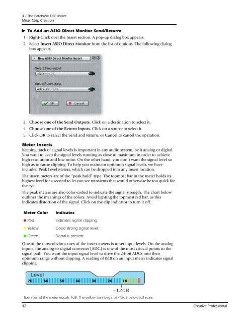
To Add an ASIO Direct Monitor Send/Return:<br />
1. Right-Click over the Insert section. A pop-up dialog box appears.<br />
2. Select Insert ASIO Direct Monitor from the list of options. The following dialog<br />
box appears.<br />
3. Choose one of the Send Outputs. Click on a destination to select it.<br />
4. Choose one of the Return <strong>Input</strong>s. Click on a source to select it.<br />
5. Click OK to select the Send and Return, or Cancel to cancel the operation.<br />
Meter Inserts<br />
Keeping track of signal levels is important in any audio system, be it analog or digital.<br />
You want to keep the signal levels running as close to maximum in order to achieve<br />
high resolution and low noise. On the other hand, you don’t want the signal level so<br />
high as to cause clipping. To help you maintain optimum signal levels, we have<br />
included Peak Level Meters, which can be dropped into any insert location.<br />
The insert meters are of the “peak hold” type. The topmost bar in the meter holds its<br />
highest level for a second to let you see transients that would otherwise be too quick for<br />
the eye.<br />
The peak meters are also color-coded to indicate the signal strength. The chart below<br />
outlines the meanings of the colors. Avoid lighting the topmost red bar, as this<br />
indicates distortion of the signal. Click on the clip indicator to turn it off.<br />
Meter Color Indicates<br />
Red Indicates signal clipping.<br />
Yellow Good strong signal level.<br />
Green Signal is present.<br />
One of the most obvious uses of the insert meters is to set input levels. On the analog<br />
inputs, the analog-to-digital converter (ADC) is one of the most critical points in the<br />
signal path. You want the input signal level to drive the 24-bit ADCs into their<br />
optimum range without clipping. A reading of 0dB on an input meter indicates signal<br />
clipping.<br />
70<br />
Level<br />
60<br />
50<br />
40<br />
30<br />
20<br />
10<br />
--12dB<br />
Each bar of the meter equals 1dB. The yellow bars begin at -12dB below full scale.<br />
42 <strong>Creative</strong> Professional