Architecture Modeling - SPES 2020
Architecture Modeling - SPES 2020
Architecture Modeling - SPES 2020

You also want an ePaper? Increase the reach of your titles
YUMPU automatically turns print PDFs into web optimized ePapers that Google loves.
ReusableElement<br />
ComData<br />
+com Data 1<br />
+referencedPorts<br />
0..*<br />
PortReference<br />
Signal<br />
+ length: int<br />
Message<br />
+ length: int<br />
Frame<br />
+ length: int<br />
<strong>Architecture</strong> <strong>Modeling</strong><br />
+signal<br />
1<br />
+owner +signalT oMsgMapping<br />
+message<br />
1<br />
+owner +msgT oFrameM apping<br />
NamedElement<br />
MsgToFrameMapping<br />
0..*<br />
+ offsetInFrame: int<br />
0..*<br />
«enumeration»<br />
TransferPropertyKind<br />
«enum eration»<br />
triggered<br />
pending<br />
triggeredOnChange<br />
SignalToMsgM apping<br />
NamedElement<br />
+ offsetInMessage: int<br />
+ transferProperty: T ransferPropertyKind<br />
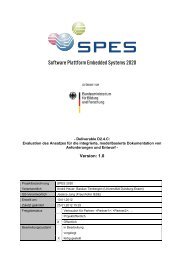
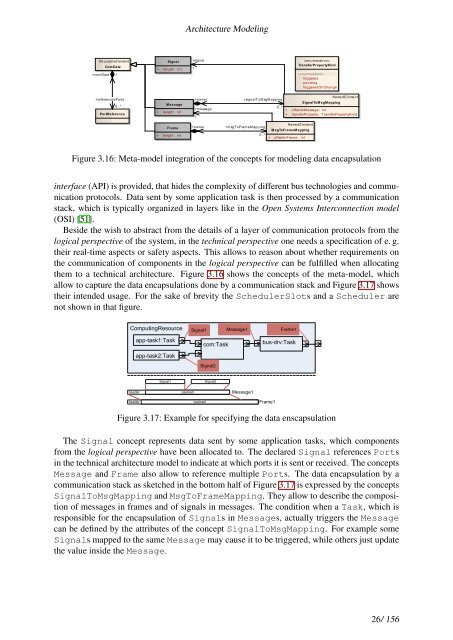
Figure 3.16: Meta-model integration of the concepts for modeling data encapsulation<br />
interface (API) is provided, that hides the complexity of different bus technologies and communication<br />
protocols. Data sent by some application task is then processed by a communication<br />
stack, which is typically organized in layers like in the Open Systems Interconnection model<br />
(OSI) [51].<br />
Beside the wish to abstract from the details of a layer of communication protocols from the<br />
logical perspective of the system, in the technical perspective one needs a specification of e. g.<br />
their real-time aspects or safety aspects. This allows to reason about whether requirements on<br />
the communication of components in the logical perspective can be fulfilled when allocating<br />
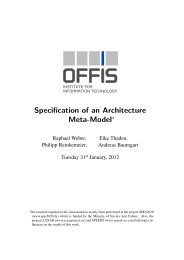
them to a technical architecture. Figure 3.16 shows the concepts of the meta-model, which<br />
allow to capture the data encapsulations done by a communication stack and Figure 3.17 shows<br />
their intended usage. For the sake of brevity the SchedulerSlots and a Scheduler are<br />
not shown in that figure.<br />
ComputingResource<br />
header<br />
header<br />
app-task1:Task<br />
app-task2:Task<br />
Signal1<br />
com:Task<br />
Signal2<br />
Signal1 Signal2<br />
payload<br />
Message1 Frame1<br />
Message1<br />
payload Frame1<br />
bus-drv:Task<br />
Figure 3.17: Example for specifying the data enscapsulation<br />
The Signal concept represents data sent by some application tasks, which components<br />
from the logical perspective have been allocated to. The declared Signal references Ports<br />
in the technical architecture model to indicate at which ports it is sent or received. The concepts<br />
Message and Frame also allow to reference multiple Ports. The data encapsulation by a<br />
communication stack as sketched in the bottom half of Figure 3.17 is expressed by the concepts<br />
SignalToMsgMapping and MsgToFrameMapping. They allow to describe the composition<br />
of messages in frames and of signals in messages. The condition when a Task, which is<br />
responsible for the encapsulation of Signals in Messages, actually triggers the Message<br />
can be defined by the attributes of the concept SignalToMsgMapping. For example some<br />
Signals mapped to the same Message may cause it to be triggered, while others just update<br />
the value inside the Message.<br />
26/ 156