Architecture Modeling - SPES 2020
Architecture Modeling - SPES 2020
Architecture Modeling - SPES 2020

Create successful ePaper yourself
Turn your PDF publications into a flip-book with our unique Google optimized e-Paper software.
<strong>Architecture</strong> <strong>Modeling</strong><br />
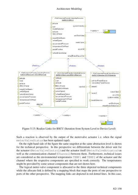
Figure 5.13: Realize Links for BSCU (Iteration from System Level to Device Level)<br />
Such a reaction is observed by the output of the metervalve actuator i. e. when the signal<br />
meterValveStatus has been updated (upd).<br />
On the right hand side of the figure the same snapshot at the same abstraction level is shown<br />
for the technical perspective. In this perspective we differentiate between the driver unit for<br />
the actuator (MeterValveControl) and the actuator itself (MeterValveActuator) as<br />
well as the communication channel (Channel) between them. Furthermore, technical issues<br />
are considered as the environmental temperatures TEMP1 and TEMP2 of the actuator and the<br />
channel where the respective components are specified to work correctly. The temperatures<br />
might be provided by some sensor components that are not shown here.<br />
The logical meter-valve component is allocated to the three depicted technical components<br />
while the allocate-link is defined by a mapping block that maps the ports of one perspective to<br />
ports of the other perspective. The mapping links are depicted in red dotted lines. In this case,<br />
82/ 156