Architecture Modeling - SPES 2020
Architecture Modeling - SPES 2020
Architecture Modeling - SPES 2020

You also want an ePaper? Increase the reach of your titles
YUMPU automatically turns print PDFs into web optimized ePapers that Google loves.
Pwr1 Pedal_Pos1 Pwr2 Pedal_Pos2<br />
CMD_AS1<br />
BSCU<br />
Monitor 1<br />
BSCU1<br />
AS1<br />
Valid1<br />
Valid2<br />
Valid_<br />
Switch<br />
Monitor 2<br />
BSCU2<br />
Command 1 Command 2<br />
CMD_AS2<br />
AS2<br />
Select_Switch<br />
<strong>Architecture</strong> <strong>Modeling</strong><br />
Valid<br />
AS<br />
CMD_AS<br />
Shut Off<br />
Selector<br />
Valve<br />
Green<br />
Pump<br />
Normal<br />
Meter<br />
Valve<br />
Isolation<br />
Valve<br />
Selector<br />
Valve<br />
Anti Skid<br />
Shut Off<br />
Valve<br />
Meter<br />
Valve<br />
Blue<br />
Pump<br />
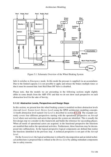
Figure 5.1: Schematic Overview of the Wheel Braking System<br />
Alternate<br />
Reserve<br />
Accumulator<br />
Mech Pedal Position<br />
Wheel<br />
fails it switches to Emergency mode. In this mode the pressure is supplied via an accumulator.<br />
Due to the limited capacity it is not possible to apply and release the brakes multiple times so<br />
that it must be ensured that Anti-Skid Shut-Off Valve is disabled.<br />
Please note, that the models we are presenting in the following sections might slightly<br />
differ in some details from the ARP 4761 and that we do not show each perspective on each<br />
abstraction level for the sake of brevity.<br />
5.1.3.2 Abstraction Levels, Perspectives and Design Steps<br />
In this section, we present how the wheel braking system is modeled on three abstraction levels<br />
(Aircraft Level, System Level, Device Level) using the <strong>SPES</strong> architecture modeling concepts.<br />
A fourth abstraction level named Unit Level is described in section 5.1.3.5. The example currently<br />
covers four different perspectives starting with the operational perspective on Aircraft<br />
Level where user-activities and actors that operate the system are identified. This is usually the<br />
first design-step we consider in this framework and builds the reference for succeeding phases.<br />
When all needs of operational actors are acquired, in the functional perspective the functions<br />
are modeled that realize the operational activities. Furthermore, these functions may be decomposed<br />
into subfunctions. In the logical perspective logical components are defined that realize<br />
the functions identified in the previous step. A technical perspective is not part of the Aircraft<br />
Level.<br />
On the System Level, the logical architecture is refined by decomposition and an initial technical<br />
architecture is proposed that is refined at the Device Level by adding redundant components<br />
due to safety reasons.<br />
73/ 156