Architecture Modeling - SPES 2020
Architecture Modeling - SPES 2020
Architecture Modeling - SPES 2020

Create successful ePaper yourself
Turn your PDF publications into a flip-book with our unique Google optimized e-Paper software.
LSI 1<br />
<strong>Architecture</strong> <strong>Modeling</strong><br />
• The hardware perspective in which the connections between the sensors and the computers<br />
have to be found<br />
• The geometrical perspective which gives the possibility to evaluate the result of connections<br />
by allowing to express distances and length for the cables<br />
Accel. Left<br />
Sensor<br />
Left Side<br />
Impact<br />
Logical Perspective Technical Perspective Geometrical Perspective<br />
Pressure Left<br />
Sensor<br />
Redundant<br />
Airbag System<br />
Right Side<br />
Impact<br />
Front<br />
Impact<br />
LSI 2 RSI 1 RSI 2 FI 1 FI 2<br />
… …<br />
<br />
Decomposition<br />
…<br />
Pressure Front<br />
Sensor<br />
Pressure Front<br />
Sensor<br />
Independence constraint<br />
Port<br />
ECU1<br />
Accel. Sensor<br />
Front Type<br />
ECU Type<br />
ASF1 ASF2 ASF3 ASF4<br />
Acceleration<br />
Sensor Type<br />
ECU2 ECU3 ECU4<br />
Accel. Sensor<br />
Left Type<br />
Sensor<br />
Type<br />
<br />
Inheritance<br />
Accel. Sensor<br />
Right …<br />
Pressure<br />
Sensor Type<br />
…<br />
Acceleration Sensor<br />
Pressure Sensor<br />
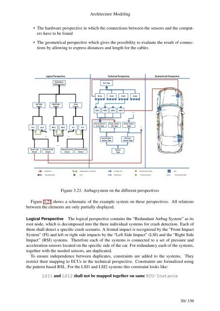
Figure 3.21: Airbagsystem on the different perspectives<br />
(x,y,z)<br />
(x,y,z)<br />
(x,y,z)<br />
(x,y,z)<br />
ECU<br />
Connection/Cable<br />
Figure 3.21 shows a schematic of the example system on these perspectives. All relations<br />
between the elements are only partially displayed.<br />
Logical Perspective The logical perspective contains the “Redundant Airbag System” as its<br />
root node, which is decomposed into the three individual systems for crash detection. Each of<br />
them shall detect a specific crash scenario. A frontal impact is recognized by the “Front Impact<br />
System” (FI) and left or right side impacts by the “Left Side Impact” (LSI) and the “Right Side<br />
Impact” (RSI) systems. Therefore each of the systems is connected to a set of pressure and<br />
acceleration sensors located on the specific side of the car. For redundancy each of the systems,<br />
together with the needed sensors, are duplicated.<br />
To ensure independence between duplicates, constraints are added to the systems. They<br />
restrict their mapping to ECUs in the technical perspective. Constraints are formalized using<br />
the pattern based RSL. For the LSI1 and LSI2 systems this constraint looks like:<br />
LSI1 and LSI2 shall not be mapped together on same ECU-Instance<br />
30/ 156