Architecture Modeling - SPES 2020
Architecture Modeling - SPES 2020
Architecture Modeling - SPES 2020

You also want an ePaper? Increase the reach of your titles
YUMPU automatically turns print PDFs into web optimized ePapers that Google loves.
<strong>Architecture</strong> <strong>Modeling</strong><br />
of modeling artefacts in Orca is listed. The Orca tasks correspond to the components of the<br />
logical perspective in the <strong>SPES</strong> metamodel that are allocated on the task components of the<br />
technical perspective i.e. we have four tasks namely Command1, Monitor1, Command2<br />
and Monitor2 building the two channels. For each channel, there exists a trigger node emitting<br />
activation events with a certain period and jitter. Period and jitter are derived from the<br />
assumptions of the triggered tasks Command1 and Command2 i.e. here both triggers produce<br />
activation events with a period of 5 milliseconds. The communication between tasks is modeled<br />
by signals in Orca which correspond to the communication components of the logical perspective<br />
namely Com1ToMon1 and Com2ToMon2. The execution times for tasks were annotated<br />
as attributes in the <strong>SPES</strong> model and translated to attributes of the Orca task nodes.<br />
In the middle of the figure, the hardware architecture is depicted consisting of the two ECUs<br />
ECU1 and ECU2. Each ECU has an ECUServer that implements the scheduler component<br />
of the <strong>SPES</strong> model. Accordingly, each ECU-server contains two scheduler slots. Each task is<br />
mapped to exactly one of these scheduler slots in the same way as described in Figure 5.20.<br />
This mapping leads to the fact that each signal has to be transmitted using the bus component<br />
CANBus which is part of the hardware architecture in Orca and offers a BusServer that<br />
schedules two bus slots. The mapping of signals to bus slots is realized using messages. Each<br />
signal that is not local is linked to a message and each message is mapped to a bus slot. The<br />
mapping is not shown here explicitly.<br />
The contracts of the <strong>SPES</strong> model are represented in different ways. First, as already mentioned,<br />
the assumptions of triggered tasks are realized by their trigger nodes. The contracts<br />
that define local deadlines for tasks or signals are realized by setting the deadline attribute of<br />
the Orca nodes to the appropriate value. Contracts that define (non-local) deadlines over several<br />
tasks or signals are modeled by end-to-end deadlines in the Orca model. There exist two<br />
end-to-end deadlines, one for each channel, named according to the contracts they stem from.<br />
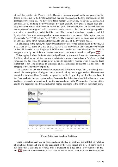
Figure 5.23: Orca Deadline Violation<br />
Using scheduling analysis, we now can check whether all contracts are fulfilled i.e. whether<br />
all deadlines (local and end-to-end deadlines) of the Orca model are met. If there exists a<br />
run such that a deadline is violated this is indicated by a red skull. For example, in Figure<br />
5.22 the end-to-end deadline BSCUContractChannel1 and the local deadlines of the<br />
92/ 156