Architecture Modeling - SPES 2020
Architecture Modeling - SPES 2020
Architecture Modeling - SPES 2020

Create successful ePaper yourself
Turn your PDF publications into a flip-book with our unique Google optimized e-Paper software.
<strong>Architecture</strong> <strong>Modeling</strong><br />
sults from the FTA will then be used to show that the contracts C3 and C4 are satisfied. As a<br />
Top-Level Event (TLE) in the FTA we will use the formalisation of the failure condition Loss of<br />
wheel braking.<br />
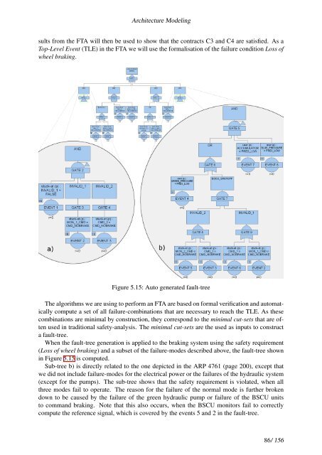
Figure 5.15: Auto generated fault-tree<br />
The algorithms we are using to perform an FTA are based on formal verification and automatically<br />
compute a set of all failure-combinations that are necessary to reach the TLE. As these<br />
combinations are minimal by construction, they correspond to the minimal cut-sets that are often<br />
used in traditional safety-analysis. The minimal cut-sets are the used as inputs to construct<br />
a fault-tree.<br />
When the fault-tree generation is applied to the braking system using the safety requirement<br />
(Loss of wheel braking) and a subset of the failure-modes described above, the fault-tree shown<br />
in Figure 5.15 is computed.<br />
Sub-tree b) is directly related to the one depicted in the ARP 4761 (page 200), except that<br />
we did not include failure-modes for the electrical power or the failures of the hydraulic system<br />
(except for the pumps). The sub-tree shows that the safety requirement is violated, when all<br />
three modes fail to operate. The reason for the failure of the normal mode is further broken<br />
down to be caused by the failure of the green hydraulic pump or failure of the BSCU units<br />
to command braking. Note that this also occurs, when the BSCU monitors fail to correctly<br />
compute the reference signal, which is covered by the events 5 and 2 in the fault-tree.<br />
86/ 156