Architecture Modeling - SPES 2020
Architecture Modeling - SPES 2020
Architecture Modeling - SPES 2020

You also want an ePaper? Increase the reach of your titles
YUMPU automatically turns print PDFs into web optimized ePapers that Google loves.
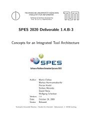
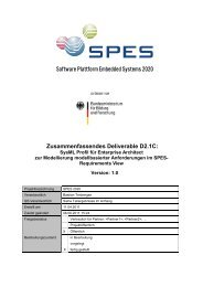
AirTempSystem<br />
C1<br />
C<br />
temp occurs each 50ms<br />
temp occurs each 50ms<br />
with jitter 5ms<br />
C2<br />
<strong>Architecture</strong> <strong>Modeling</strong><br />
Delay between temp and actTemp within [5ms,7ms]<br />
actTemp occurs each<br />
50ms with jitter 10ms<br />
temp actTemp<br />
Capture<br />
Delay between temp and control within [15ms,20ms]<br />
Delay between actTemp and control within [10ms,12ms]<br />
AirTempControl<br />
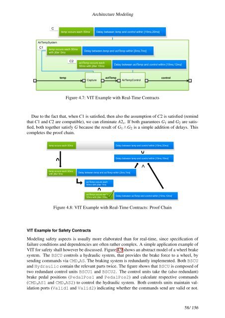
Figure 4.7: VIT Example with Real-Time Contracts<br />
control<br />
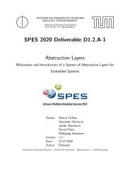
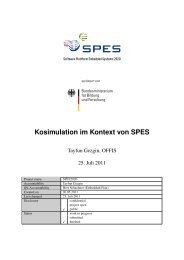
Due to the fact that, when C1 is satisfied, then also the assumption of C2 is satisfied (remind<br />
that C1 and C2 are compatible), we can eliminate A2s. If both guarantees G1 and G2 are satisfied,<br />
both together satisfy G because the result of G1 ∧ G2 is a simple addition of delays. This<br />
completes the proof chain.<br />
temp occurs each 50ms<br />
temp occurs each 50ms<br />
with jitter 5ms<br />
Delay between temp and actTemp within [5ms,7ms]<br />
actTemp occurs each<br />
50ms with jitter 7ms<br />
actTemp occurs each<br />
50ms with jitter 10ms<br />
!<br />
Delay between temp and control within [15ms,20ms]<br />
Delay between temp and control within [15ms,19ms]<br />
"<br />
Delay between actTemp and control within [10ms,12ms]<br />
Figure 4.8: VIT Example with Real-Time Contracts: Proof Chain<br />
VIT Example for Safety Contracts<br />
<strong>Modeling</strong> safety aspects is usually more elaborated than for real-time, since specification of<br />
failure conditions and dependencies are often rather complex. A simple application example of<br />
VIT for safety shall however be discussed. Figure 4.9 shows an abstract model of a wheel brake<br />
system. The BSCU controls a hydraulic system, that provides the brake force to a wheel, by<br />
sending commands via CMD AS. The braking system is redundantly implemented. Both BSCU<br />
and Hydraulic contain the relevant parts twice. The figure shows that BSCU is composed of<br />
two redundant control units BSCU1 and BSCU2. The control units take the (also redundant)<br />
brake pedal positions (PedalPos1 and PedalPos2) and calculate respective commands<br />
(CMD AS1 and CMD AS2) to control the hydraulic system. Both controls units maintain validation<br />
ports (Valid1 and Valid2) indicating whether the commands send are valid or not.<br />
58/ 156