Architecture Modeling - SPES 2020
Architecture Modeling - SPES 2020
Architecture Modeling - SPES 2020

Create successful ePaper yourself
Turn your PDF publications into a flip-book with our unique Google optimized e-Paper software.
<strong>Architecture</strong> <strong>Modeling</strong><br />
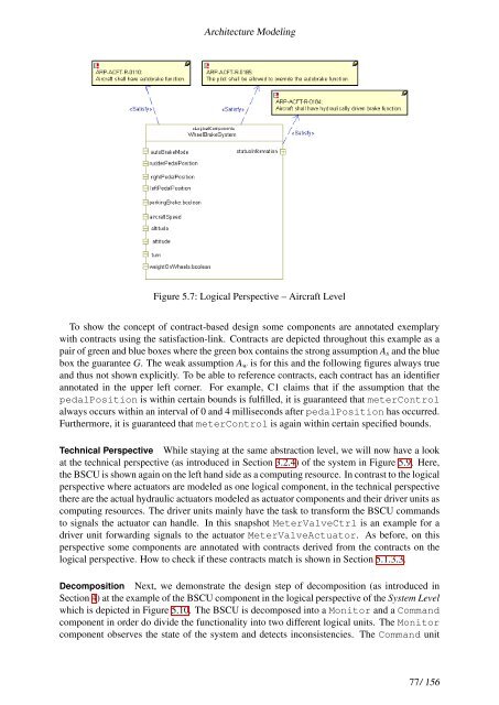
Figure 5.7: Logical Perspective – Aircraft Level<br />
To show the concept of contract-based design some components are annotated exemplary<br />
with contracts using the satisfaction-link. Contracts are depicted throughout this example as a<br />
pair of green and blue boxes where the green box contains the strong assumption As and the blue<br />
box the guarantee G. The weak assumption Aw is for this and the following figures always true<br />
and thus not shown explicitly. To be able to reference contracts, each contract has an identifier<br />
annotated in the upper left corner. For example, C1 claims that if the assumption that the<br />
pedalPosition is within certain bounds is fulfilled, it is guaranteed that meterControl<br />
always occurs within an interval of 0 and 4 milliseconds after pedalPosition has occurred.<br />
Furthermore, it is guaranteed that meterControl is again within certain specified bounds.<br />
Technical Perspective While staying at the same abstraction level, we will now have a look<br />
at the technical perspective (as introduced in Section 3.2.4) of the system in Figure 5.9. Here,<br />
the BSCU is shown again on the left hand side as a computing resource. In contrast to the logical<br />
perspective where actuators are modeled as one logical component, in the technical perspective<br />
there are the actual hydraulic actuators modeled as actuator components and their driver units as<br />
computing resources. The driver units mainly have the task to transform the BSCU commands<br />
to signals the actuator can handle. In this snapshot MeterValveCtrl is an example for a<br />
driver unit forwarding signals to the actuator MeterValveActuator. As before, on this<br />
perspective some components are annotated with contracts derived from the contracts on the<br />
logical perspective. How to check if these contracts match is shown in Section 5.1.3.3.<br />
Decomposition Next, we demonstrate the design step of decomposition (as introduced in<br />
Section 4) at the example of the BSCU component in the logical perspective of the System Level<br />
which is depicted in Figure 5.10. The BSCU is decomposed into a Monitor and a Command<br />
component in order do divide the functionality into two different logical units. The Monitor<br />
component observes the state of the system and detects inconsistencies. The Command unit<br />
77/ 156