Architecture Modeling - SPES 2020
Architecture Modeling - SPES 2020
Architecture Modeling - SPES 2020

You also want an ePaper? Increase the reach of your titles
YUMPU automatically turns print PDFs into web optimized ePapers that Google loves.
<strong>Architecture</strong> <strong>Modeling</strong><br />
Figure 5.18: Technical Perspective – Unit Level – BSCU<br />
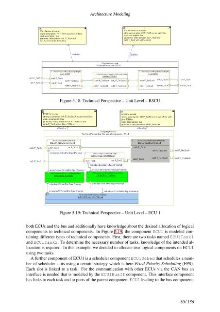
Figure 5.19: Technical Perspective – Unit Level – ECU 1<br />
both ECUs and the bus and additionally have knowledge about the desired allocation of logical<br />
components to technical components. In Figure 5.19, the component ECU1 is modeled containing<br />
different types of technical components. First, there are two tasks named ECU1Task1<br />
and ECU1Task2. To determine the necessary number of tasks, knowledge of the intended allocation<br />
is required. In this example, we decided to allocate two logical components on ECU1<br />
using two tasks.<br />
A further component of ECU1 is a scheduler component ECU1Sched that schedules a number<br />
of scheduler slots using a certain strategy which is here Fixed Priority Scheduling (FPS).<br />
Each slot is linked to a task. For the communication with other ECUs via the CAN bus an<br />
interface is needed that is modeled by the ECU1BusIf component. This interface component<br />
has links to each task and to ports of the parent component ECU1 leading to the bus component.<br />
89/ 156