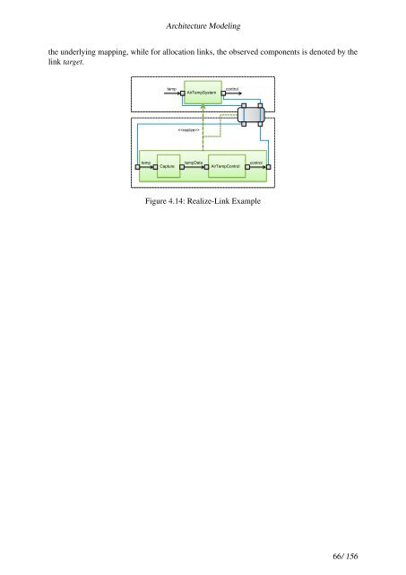
<strong>Architecture</strong> <strong>Modeling</strong> the underlying mapping, while for allocation links, the observed components is denoted by the link target. temp AirTempSystem temp tempData Capture control AirTempControl control Figure 4.14: Realize-Link Example 66/ 156
5 Using the <strong>Architecture</strong> Meta-Model Design processes for embedded systems applications differ strongly within the range of application domains considered in <strong>SPES</strong> <strong>2020</strong>. In automation applications, the geometric layout of the plant is determined early in planning stages, and defines boundary conditions for other design phases. In contrast, while of course medical devices such as pace-makers must ultimately fit into a physical packaging easily insertable into the body, other aspects such as algorithm design are more dominant. Similarly, almost no industrial application will be developed purely top-down, nor purely bottom-up, and tradeoffs such as between optimizing re-use and optimizing for performance will determine the middle-out design strategy for a particular product development. Finally, target architectures are often subject to domain specific standards, such as AUTOSAR [9] in the automotive domain, and IMA in avionics, calling for a need to support a variety of domain specific standards within the <strong>SPES</strong> <strong>Architecture</strong> Metamodel. The purpose of this section can thus not be to describe something as “the <strong>SPES</strong> design process”. Rather, the purpose of this section is to show how a broad variety of design styles and design processes can be naturally expressed using the key concepts of the <strong>SPES</strong> <strong>Architecture</strong> Metamodel. An orthogonal aspect covered in this section relates to the advocation of a contract-based design style. We highlight, how typical design steps in industrial processes can benefit from contract-based design, thus motivating the anchoring of this design paradigm in the <strong>SPES</strong> metamodel. We cover these orthogonal aspects in separate sections. The style of writing is chosen so as to address a typical systems engineer. Having read the quick tour (Section 2) is an indispensable prerequisite for this section. Readers who are interested in more formal treatments of the mentioned design steps are referred to Section 4 – “Steps in component based design” – and its mathematical foundation given in the annex. 5.1 On the Role of Perspectives and Abstraction Layers 5.1.1 What We Can Learn from the EDA Domain Electronic design automation (EDA) has early adopted the concept of abstraction layers (to cope with complexity) and perspectives (there called “domains”) to achieve separation of concerns between different views of an integrated circuit, such as its physical layout, its logical architecture, and its behavior (see Gajski’s Y-Chart [25]). Established abstraction levels include (from lower to higher) the transistor level, the gate level, the register transfer level, the system level, and the instruction-set architecture level. Each level is essentially characterized by what is seen as a primitive building block at the chosen level of abstraction. The identity of the building block is obvious from the level name for the transistor and the gate level. For the register transfer level, these blocks include both combinational circuits such as adders, multipliers, shifters, etc., as well as sequential circuits such as latches, registers, register-files, and the various types of memory. The naming of the next higher level is predominantly used in the domain of computer architecture design, where clock-cycle accurate models describe the effect of executing instructions on the visible processor state. The term system-level, then, traditionally referred to 67/ 156