Architecture Modeling - SPES 2020
Architecture Modeling - SPES 2020
Architecture Modeling - SPES 2020

Create successful ePaper yourself
Turn your PDF publications into a flip-book with our unique Google optimized e-Paper software.
<strong>Architecture</strong> <strong>Modeling</strong><br />
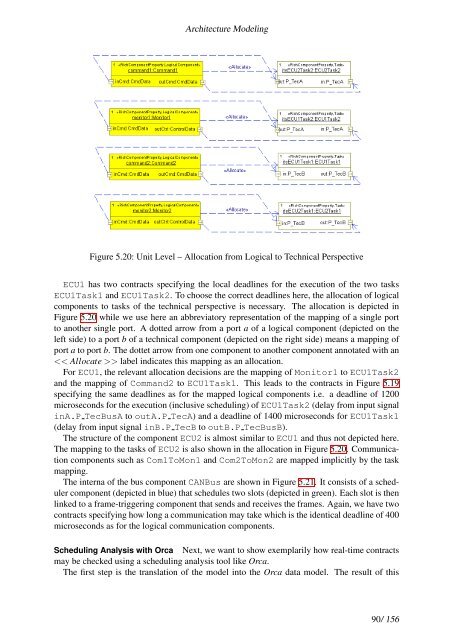
Figure 5.20: Unit Level – Allocation from Logical to Technical Perspective<br />
ECU1 has two contracts specifying the local deadlines for the execution of the two tasks<br />
ECU1Task1 and ECU1Task2. To choose the correct deadlines here, the allocation of logical<br />
components to tasks of the technical perspective is necessary. The allocation is depicted in<br />
Figure 5.20 while we use here an abbreviatory representation of the mapping of a single port<br />
to another single port. A dotted arrow from a port a of a logical component (depicted on the<br />
left side) to a port b of a technical component (depicted on the right side) means a mapping of<br />
port a to port b. The dottet arrow from one component to another component annotated with an<br />
> label indicates this mapping as an allocation.<br />
For ECU1, the relevant allocation decisions are the mapping of Monitor1 to ECU1Task2<br />
and the mapping of Command2 to ECU1Task1. This leads to the contracts in Figure 5.19<br />
specifying the same deadlines as for the mapped logical components i.e. a deadline of 1200<br />
microseconds for the execution (inclusive scheduling) of ECU1Task2 (delay from input signal<br />
inA.P TecBusA to outA.P TecA) and a deadline of 1400 microseconds for ECU1Task1<br />
(delay from input signal inB.P TecB to outB.P TecBusB).<br />
The structure of the component ECU2 is almost similar to ECU1 and thus not depicted here.<br />
The mapping to the tasks of ECU2 is also shown in the allocation in Figure 5.20. Communication<br />
components such as Com1ToMon1 and Com2ToMon2 are mapped implicitly by the task<br />
mapping.<br />
The interna of the bus component CANBus are shown in Figure 5.21. It consists of a scheduler<br />
component (depicted in blue) that schedules two slots (depicted in green). Each slot is then<br />
linked to a frame-triggering component that sends and receives the frames. Again, we have two<br />
contracts specifying how long a communication may take which is the identical deadline of 400<br />
microseconds as for the logical communication components.<br />
Scheduling Analysis with Orca Next, we want to show exemplarily how real-time contracts<br />
may be checked using a scheduling analysis tool like Orca.<br />
The first step is the translation of the model into the Orca data model. The result of this<br />
90/ 156