Architecture Modeling - SPES 2020
Architecture Modeling - SPES 2020
Architecture Modeling - SPES 2020

You also want an ePaper? Increase the reach of your titles
YUMPU automatically turns print PDFs into web optimized ePapers that Google loves.
<strong>Architecture</strong> <strong>Modeling</strong><br />
next selection. The second assertion defines what happens before this minute. Obviously, it<br />
should not be allowed that the temperature provided after a new selection becomes too high<br />
or too low (maybe due to inappropriate heating or cooling). The specification of the second<br />
guarantee thus states, that temperature fluctuation is within an appropriate range, i.e., the first<br />
momentum of some hull curve of the difference is less than 0.<br />
4.1.2 Real–Time<br />
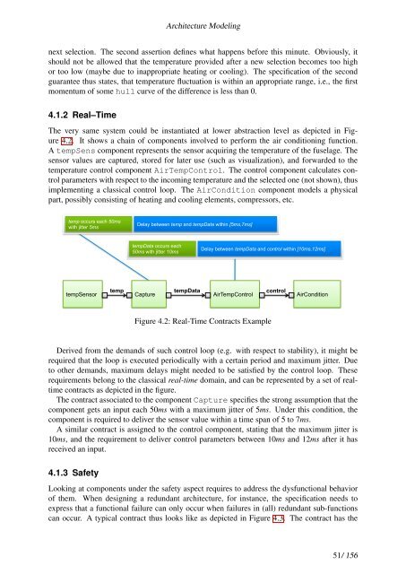
The very same system could be instantiated at lower abstraction level as depicted in Figure<br />
4.2. It shows a chain of components involved to perform the air conditioning function.<br />
A tempSens component represents the sensor acquiring the temperature of the fuselage. The<br />
sensor values are captured, stored for later use (such as visualization), and forwarded to the<br />
temperature control component AirTempControl. The control component calculates control<br />
parameters with respect to the incoming temperature and the selected one (not shown), thus<br />
implementing a classical control loop. The AirCondition component models a physical<br />
part, possibly consisting of heating and cooling elements, compressors, etc.<br />
temp occurs each 50ms<br />
with jitter 5ms<br />
tempSensor<br />
Delay between temp and tempData within [5ms,7ms]<br />
tempData occurs each<br />
50ms with jitter 10ms<br />
temp tempData<br />
Capture<br />
Delay between tempData and control within [10ms,12ms]<br />
control<br />
AirTempControl AirCondition<br />
Figure 4.2: Real-Time Contracts Example<br />
Derived from the demands of such control loop (e.g. with respect to stability), it might be<br />
required that the loop is executed periodically with a certain period and maximum jitter. Due<br />
to other demands, maximum delays might needed to be satisfied by the control loop. These<br />
requirements belong to the classical real-time domain, and can be represented by a set of realtime<br />
contracts as depicted in the figure.<br />
The contract associated to the component Capture specifies the strong assumption that the<br />
component gets an input each 50ms with a maximum jitter of 5ms. Under this condition, the<br />
component is required to deliver the sensor value within a time span of 5 to 7ms.<br />
A similar contract is assigned to the control component, stating that the maximum jitter is<br />
10ms, and the requirement to deliver control parameters between 10ms and 12ms after it has<br />
received an input.<br />
4.1.3 Safety<br />
Looking at components under the safety aspect requires to address the dysfunctional behavior<br />
of them. When designing a redundant architecture, for instance, the specification needs to<br />
express that a functional failure can only occur when failures in (all) redundant sub-functions<br />
can occur. A typical contract thus looks like as depicted in Figure 4.3. The contract has the<br />
51/ 156