special - Alu-web.de
special - Alu-web.de
special - Alu-web.de

You also want an ePaper? Increase the reach of your titles
YUMPU automatically turns print PDFs into web optimized ePapers that Google loves.
TECHNOLOGY<br />
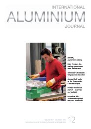
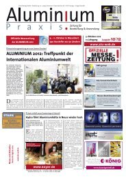
Fig. 3: A hollow copper inductor dissipates<br />
more heat, and so requires water for cooling<br />
tek stirrer generates only low I 2 R losses which<br />
an air flow at a certain speed and mass flow<br />
can easily remove. Our stirrers have been <strong>de</strong>signed<br />
to optimise this cooling air flow.<br />
For the water cooled inductor the heat<br />
generated is so much higher that air-cooling<br />
cannot remove it. This is why it needs water<br />
with all of the associated complexities of supply<br />
systems, piping, quality sealing and glands<br />
to avoid leaks, as well as emergency back-up<br />
water systems etc.<br />
The Altek air-cooling system is <strong>de</strong>signed to<br />
ensure that the heat generated by the inductor<br />
coil is easily dissipated by the cooling air flow.<br />
The variables that affect this are:<br />
• Inlet air temperature<br />
• Size of current being applied to the<br />
copper coil<br />
• Radiated heat from the furnace<br />
• Local ambient air temperature.<br />
This <strong>de</strong>sign allows the air to be applied in a<br />
<strong>special</strong> way within the inductor so as to remove<br />
the lesser heat generated by the current<br />
applied to the inductor coil. A secondary<br />
benefit of this type of coil construction is that<br />
promotes a very long life of the inductor by<br />
reducing the risk of overheating of the coil,<br />
which can easily cause serious damage to a<br />
hollow copper tube type inductor coil.<br />
As an example, the ol<strong>de</strong>st solid inductor<br />
installed in 1994 is still in operation today.<br />
Energy consumption: There has long been<br />
a myth that you need to use huge amounts<br />
of electrical energy with EM stirring technology<br />
to obtain a good mixing effect within the<br />
furnace. This may be the case with alternative<br />
<strong>de</strong>signs, but the Siber Force technology has<br />
significantly reduced the input energy nee<strong>de</strong>d<br />
to achieve efficient stirring.<br />
Thus one of the big differentiating factors<br />
of the Altek stirring technology is its lower<br />
electrical energy operating costs (due to the<br />
<strong>special</strong> inductor <strong>de</strong>sign and control system).<br />
This unique <strong>de</strong>sign and operation of the Altek<br />
technology allows very low energy operation<br />
such that some customers use less than 100<br />
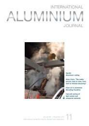
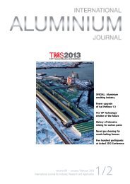
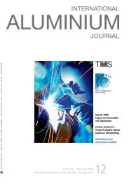
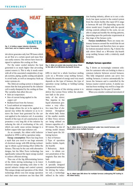
Fig. 4: Altek air-cooled si<strong>de</strong>-mounted stirrer fitted<br />
to the si<strong>de</strong> of an 80-tonne dry-hearth furnace<br />
kWh in total for a whole four-hour melting<br />
cycle on a 50-tonne scrap melting furnace.<br />
Clearly the amount of energy used very much<br />
<strong>de</strong>pends on the type of furnace, the type of<br />
operation (scrap melting or holding / casting<br />
furnace) etc.<br />
The key focus of this stirring system is to<br />
<strong>de</strong>liver the Lorenz Force within the aluminium<br />
bath in the proximity<br />
of the stirrer.<br />
This impetus in the<br />
liquid aluminium generates<br />
a very effective<br />
mass flow of aluminium<br />
throughout<br />
© Altek<br />
the whole bath. Some<br />
of the smaller mo<strong>de</strong>ls<br />
of Siber Force stirrers<br />
are being utilised on<br />
furnace capacities of ><br />
60 tonnes. The size of<br />
stirring mo<strong>de</strong>l chosen<br />
is based upon the following<br />
factors:<br />
1. Size of furnace<br />
2. Type of operation<br />
(melter, hol<strong>de</strong>r, liquid,<br />
dry hearth)<br />
3. Refractory thickness<br />
– to obtain correct<br />
penetration of the<br />
magnetic flux into the<br />
bath<br />
4. Available space.<br />
A <strong>special</strong>ly <strong>de</strong>signed<br />
and patented technique<br />
for driving the inductor<br />
coil, a technology<br />
utilised in the induction<br />
heating industry, allows us to use a relatively<br />
low input current to the control system<br />
from the clients facility (the input kVA range<br />
is between 80 and 150 <strong>de</strong>pending upon the<br />
stirrer mo<strong>de</strong>l size). Coupled with the <strong>special</strong><br />
stirring controls utilised in the cycle, we are<br />
able to adapt and modify the stirring patterns,<br />
<strong>de</strong>pending upon the particular requirement at<br />
that stage of the furnace cycle.<br />
Furnace installations: There are many stationary<br />
furnaces around the world that do not<br />
have basements and therefore have no space<br />
for bottom-mounted stirrers. Fig. 4 shows the<br />
si<strong>de</strong> stirrer fitted on a 80-tonne dry-hearth<br />
scrap melting furnace with a relatively small<br />
footprint.<br />
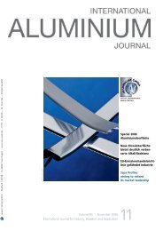
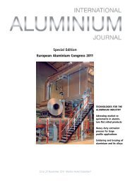
Multiple furnace operation<br />
Fig. 5 shows an increasingly common solution<br />
for customers who are looking to share a<br />
common inductor between several furnaces.<br />
This fully integrated system can serve two<br />
melting furnaces; it moves automatically between<br />
the furnaces and is controlled by the<br />
furnace master control system. A similar system<br />
has been working very well in a large aluminium<br />
company for the past 12 months.<br />
When you consi<strong>de</strong>r continual movement of<br />
Fig. 5: Altek stirrer in stirrer basement un<strong>de</strong>r two reverb furnaces, and<br />
<strong>de</strong>signed to serve multiple furnaces<br />
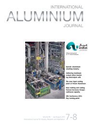
Fig. 6: Altek type 500 stirrer for multiple furnaces un<strong>de</strong>rgoing FAT testing in<br />
the Altek factory<br />
50 ALUMINIUM · 3/2013