Lockout / Tagout - Ohio Bureau of Workers' Compensation
Lockout / Tagout - Ohio Bureau of Workers' Compensation
Lockout / Tagout - Ohio Bureau of Workers' Compensation
You also want an ePaper? Increase the reach of your titles
YUMPU automatically turns print PDFs into web optimized ePapers that Google loves.
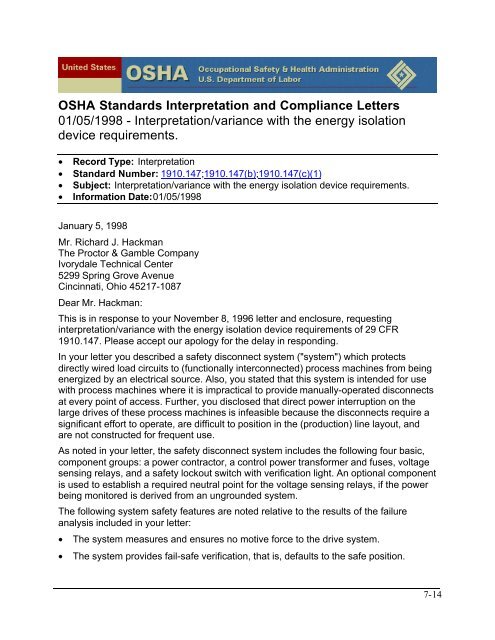
OSHA Standards Interpretation and Compliance Letters<br />
01/05/1998 - Interpretation/variance with the energy isolation<br />
device requirements.<br />
• Record Type: Interpretation<br />
• Standard Number: 1910.147;1910.147(b);1910.147(c)(1)<br />
• Subject: Interpretation/variance with the energy isolation device requirements.<br />
• Information Date:01/05/1998<br />
January 5, 1998<br />
Mr. Richard J. Hackman<br />
The Proctor & Gamble Company<br />
Ivorydale Technical Center<br />
5299 Spring Grove Avenue<br />
Cincinnati, <strong>Ohio</strong> 45217-1087<br />
Dear Mr. Hackman:<br />
This is in response to your November 8, 1996 letter and enclosure, requesting<br />
interpretation/variance with the energy isolation device requirements <strong>of</strong> 29 CFR<br />
1910.147. Please accept our apology for the delay in responding.<br />
In your letter you described a safety disconnect system ("system") which protects<br />
directly wired load circuits to (functionally interconnected) process machines from being<br />
energized by an electrical source. Also, you stated that this system is intended for use<br />
with process machines where it is impractical to provide manually-operated disconnects<br />
at every point <strong>of</strong> access. Further, you disclosed that direct power interruption on the<br />
large drives <strong>of</strong> these process machines is infeasible because the disconnects require a<br />
significant effort to operate, are difficult to position in the (production) line layout, and<br />
are not constructed for frequent use.<br />
As noted in your letter, the safety disconnect system includes the following four basic,<br />
component groups: a power contractor, a control power transformer and fuses, voltage<br />
sensing relays, and a safety lockout switch with verification light. An optional component<br />
is used to establish a required neutral point for the voltage sensing relays, if the power<br />
being monitored is derived from an ungrounded system.<br />
The following system safety features are noted relative to the results <strong>of</strong> the failure<br />
analysis included in your letter:<br />
• The system measures and ensures no motive force to the drive system.<br />
• The system provides fail-safe verification, that is, defaults to the safe position.<br />
7-14


