- Page 3:
ORNL/TM-11039 Metals and Ceramics D
- Page 6 and 7:
Page 9.3 Composite Fabrication . .
- Page 9:
LIST OF TABLES Table Page 5,l. Prop
- Page 12 and 13:
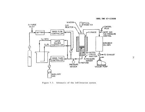
Figure 8.3. 9.1.. 9.2. 9.3. 9.4. 9.
- Page 14 and 15:
Figure 10.18. 10.19. 10.20. 10. 21.
- Page 17 and 18:
ACKNOWLEDGMENTS The author wishes t
- Page 19 and 20:
CWCTERIZATION AND CONTROL OF THE FI
- Page 21:
1. INTRODUCTION During the last sev
- Page 24 and 25:
The development of low-density, hig
- Page 27 and 28:
3. FABRICATION TECHNIQUES 3.1 Intro
- Page 29 and 30:
11 isostatic pressing (HIP), can be
- Page 31:
13 utilizing the comparatively low-
- Page 34 and 35:
16 ORN L- DWG 85- 4 i 4 18RS HEAT1
- Page 37 and 38:
5. COMPOSITE DESIGN 5.1 Introductio
- Page 39 and 40:
21 5,2 Mechanical Considerations Th
- Page 41 and 42: 23 GRNL-DWG 88-74 26 Figure 5.1. Th
- Page 43 and 44: 25 Equation (6) shows that the stre
- Page 45 and 46: 27 of reinforcement. There are two
- Page 47 and 48: 29 in strength. Conversely, the fib
- Page 49 and 50: -I_- Table 5.2. Thermally induced a
- Page 51 and 52: 33 1.2 ID 0.8 ;.r 1 e fi v 0.6 a4 Q
- Page 53: 35 will affect the interface and, t
- Page 56 and 57: 38 fiber-matrix bonding; thus, a fu
- Page 58 and 59: 40 In the analysis of the mechanica
- Page 60 and 61: 42 1.2 I .o .6 - E f aa '3 0.6 cn 3
- Page 62 and 63: 44 will result in the matrix being
- Page 64 and 65: I I MATRIX MATRIX Figure 7.1. Schem
- Page 66 and 67: 48 F = 2a2H, where H is the hardnes
- Page 68 and 69: 50 OWL-PHOTO 6866-86 i d c I 20pm F
- Page 70 and 71: 52 where Af is the surface area of
- Page 72 and 73: 54 Figure 7.4. Tensile and shear st
- Page 74 and 75: 56 I I I / -c rc -c / . Om / / I /
- Page 76 and 77: 58 ORNL-OWG 87-i 8234 F Figure 7.7.
- Page 78 and 79: coating and the distribution of she
- Page 80 and 81: 62 O m PHOTO 6676-87 i SIC FIBERS -
- Page 83 and 84: the composite, therefore an interme
- Page 85 and 86: methane as the reactant and is, thu
- Page 87 and 88: 9. EXPERIMENTAL PROCEDURES 9.1 Depo
- Page 89 and 90: 71 furnace. The furnace is, therefo
- Page 91: 73 further protection. A 6.5-cm-dia
- Page 95 and 96: 77 was not deoxygenated. Other gase
- Page 97 and 98: 79 Y201840 Y201841 Figure 9.5. Grap
- Page 99 and 100: 81 Table 9.1. Precoating processing
- Page 101 and 102: 83 9.4 Mechanical ProDerties 9.4.1
- Page 103 and 104: 85 true tensile strength of a compo
- Page 105 and 106: 87 .. h 8 o La z 4J u 4 k 4 4
- Page 107 and 108: 89 cut surface. This alignment is e
- Page 109 and 110: 91 YP5199 YP5200 *I Figure 9.8. Pho
- Page 111 and 112: 93 the cracks. In addition, if the
- Page 113 and 114: 10. RESULTS 10.1 ComDosite ProDerti
- Page 116 and 117: 98 Table 10.1. Property summary for
- Page 118 and 119: 100 Table 10.2. Interfacial frictio
- Page 120 and 121: , - - I e-, 75 ORNL-DWG 87-15948R C
- Page 122 and 123: I 104 I I 1 I rr) '0
- Page 124 and 125: OANL-DWC 88-6289 I I I I I I I I I
- Page 126 and 127: 108 A rl A r
- Page 128 and 129: 110 steps demonstrates that silicon
- Page 130 and 131: 112 t Figure 10.8. The presence of
- Page 132 and 133: 114 c Figure 10.10. SEM micrograph
- Page 134 and 135: 116 Table 10.5. Thermochemical eval
- Page 136 and 137: 118 microprobe was not equipped to
- Page 138 and 139: 350 300 CVI- 175 RAT. 175201 I 250
- Page 140 and 141: 122 (N) OVOl
- Page 142 and 143:
124 Table 10.6. Thermochemical eval
- Page 144 and 145:
126 predicted weight loss was 3%. T
- Page 146 and 147:
I F Figure 10.17. SEM micrographs o
- Page 148 and 149:
3 130 87 1 I I .C b Y --Q) -w -e -N
- Page 150 and 151:
132 Table 10.7. Thermochemical eval
- Page 153 and 154:
ORNL-OW 88-6289 ORNL-Dwc 88-6294 BU
- Page 155 and 156:
137 Table 10.8. Boron nitride coati
- Page 157 and 158:
139 RAL 102744 Figure 10.23. SEM mi
- Page 159 and 160:
141 infiltration by the preferred p
- Page 161 and 162:
143 YP 4971 YP 4970 Figure 10.25. C
- Page 163:
1 $1 0 *- QI 12 U 8 Pl 145 1 $1 0 T
- Page 166 and 167:
148 The resultant fibers are compos
- Page 168 and 169:
150 Table 11.1. Properties of Sic.
- Page 170 and 171:
152 Table 11.2. The influence of in
- Page 172 and 173:
154 11.2.2 Fracture stress and Youn
- Page 174 and 175:
156 ORNL-DWG 88-6276 MATRIX CRACKIN
- Page 176 and 177:
158 As previously discussed, the ul
- Page 178 and 179:
160 Fiber length becomes important
- Page 180 and 181:
162 upon matrix failure. This is th
- Page 182 and 183:
164 ORNL-DWG 88-747iR -10 -12 -4 4
- Page 184 and 185:
as-received fibers have a slightly
- Page 186 and 187:
168 throughout the composite sample
- Page 188 and 189:
170 SHEAR STRESS, T(MPo) 2 4 6 8 IO
- Page 190 and 191:
172 failure and extensive fiber pul
- Page 192 and 193:
174 Conversely, the individual Nica
- Page 194 and 195:
176 I 3D Figure 11.7. Stress blocks
- Page 197 and 198:
12. CONCLUSIONS AND mTTURE WORK Fab
- Page 199 and 200:
REFERENCES 1. A. H. Cotrell, "Stron
- Page 201 and 202:
183 31. J. C. Whithers, "Chemical V
- Page 203 and 204:
185 56. E. Ryskewitch, "Compressive
- Page 205 and 206:
187 85. J. F. Mandell, K. C. C. Hon
- Page 207 and 208:
Part I' 189 111. W. V. Kotlensky, "
- Page 209 and 210:
191 140. D. P. Stinton and W. J. La
- Page 211:
APPENDIX A AUGER ELECTRON SPECTROSC
- Page 214 and 215:
196 Table A-1. Auger spectral peaks
- Page 217 and 218:
APPENDIX B. DETAILS OF' THE FIBER-S
- Page 219 and 220:
QRNL/TM-11039 INTERNAL DISTRIBUTION
- Page 221 and 222:
203 109-110. BATTELLE COLUMBUS LABO
- Page 223 and 224:
205 150-152. LAJESXIDE CORPORATION,
- Page 225 and 226:
207 189. 190. 191. 192. 193. 194. 1
- Page 227:
209 218. DOE, OAK RIDGE OPERATIONS,