- Page 1 and 2: TelemetryModule MT-102 UserManual t
- Page 3 and 4: MT-102 © 2010 Inventia Ltd. Wszelk
- Page 5 and 6: 2 8.2. PARAMETER GROUPS ...........
- Page 7 and 8: 4 8.2.6.2.1.2.2.6. Alarm HiHi .....
- Page 9 and 10: 10.1.6. PORT 2 activity ...........
- Page 11 and 12: 1. Introduction Despite the explosi
- Page 13 and 14: 4.2. Resources MT-102 module's reso
- Page 15 and 16: Transmission parameters are: speed
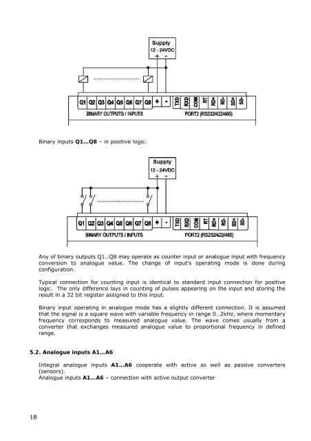
- Page 17 and 18: 4.3.6. MT2MT buffer MT2MT buffer en
- Page 19: As shown by graph, the value at whi
- Page 23 and 24: PORT 2 (RS-232/422/485 - communicat
- Page 25 and 26: part. Even with no SIM inserted, th
- Page 27 and 28: Properly inserted SIM cards secure
- Page 29 and 30: packet routing - useful for unambig
- Page 31 and 32: 7.5. Modem mode In this mode, the m
- Page 33 and 34: This mode was implemented due to re
- Page 35 and 36: Authorized numbers group - contains
- Page 37 and 38: NOTICE! Availability of parameters
- Page 39 and 40: List - All Unrestricted access for
- Page 41 and 42: 8.2.2.12. Use of SMS Function - def
- Page 43 and 44: 8.2.3.5. IP assignment Function - s
- Page 45 and 46: Range - 0.0.0.0 - 255.255.255.255 D
- Page 47 and 48: Comments - The range value defines
- Page 49 and 50: Comments - n/a 8.2.5.1.1.2. Data pa
- Page 51 and 52: number ID - ID number of device con
- Page 53 and 54: 8.2.5.4.2. Delay after error in com
- Page 55 and 56: 8.2.5.4.3.7. Force write the whole
- Page 57 and 58: Comments - value 0 (zero) forces ma
- Page 59 and 60: No Current data reading inactive De
- Page 61 and 62: 8.2.5.7.7. Number of transmission r
- Page 63 and 64: 8.2.5.9.2. Data packet delimiter Fu
- Page 65 and 66: It is recommended to set filtering
- Page 67 and 68: 8.2.6.2.1.2.2.9. Alarm LoLo Functio
- Page 69 and 70: 8.2.6.2.2.1. Name Function - allows
- Page 71 and 72:
Default value - 0 [engineering unit
- Page 73 and 74:
Comments - Function has no influenc
- Page 75 and 76:
List - Auto Data collected in Logge
- Page 77 and 78:
Default value - 0 Comments - n/a 8.
- Page 79 and 80:
Default value - . Comments - if the
- Page 81 and 82:
Default value - Bi In 0->1, Bi In 1
- Page 83 and 84:
8.2.7.3.2. Number of trials Functio
- Page 85 and 86:
For remote configuration, it is vit
- Page 87 and 88:
RS-232 Port Contains number of the
- Page 89 and 90:
Nie można wyświetlić połączone
- Page 91 and 92:
and after connecting to the module
- Page 93 and 94:
The icon on the toolbar performs sa
- Page 95 and 96:
“If” - defines the condition fo
- Page 97 and 98:
Detailed description of standard an
- Page 99 and 100:
Multiply X by Y store result (regis
- Page 101 and 102:
Mask test This function verifies wh
- Page 103 and 104:
Both 16 and 32 bit registers can be
- Page 105 and 106:
get Y: - unit number defines the nu
- Page 107 and 108:
CAUTION! All variables in Modbus ad
- Page 109 and 110:
9.12. Downloding the program After
- Page 111 and 112:
9.14.4. 2 pumps alternating action
- Page 113 and 114:
The same effect can be obtained in
- Page 115 and 116:
9.14.8. Logger program An example o
- Page 117 and 118:
10.1.3. GSM status GSM Status LEDs
- Page 119 and 120:
10.1.6. PORT 2 activity LED indicat
- Page 121 and 122:
10.1.8. SET1, SET2 alarm thresholds
- Page 123 and 124:
When GPRS LED is off the module is
- Page 125 and 126:
11. Technical data 11.1. General Di
- Page 127 and 128:
Analogue inputs AN3 … AN6: Measur
- Page 129 and 130:
12. Safety informations 12.1. Worki
- Page 131 and 132:
13.1.3.1. Advantages of GPRS techno
- Page 133 and 134:
13.2.2. Point to point communicatio
- Page 135 and 136:
without decoding of protocol. This
- Page 137 and 138:
The value may be variable or consta
- Page 139 and 140:
comment: 13.6. Data forma
- Page 141 and 142:
13.8. Trigger inputs During operati
- Page 143 and 144:
13.10. RM-120 Converter module RM-1
- Page 145 and 146:
142 0x0050 AQ1_LoLo AQ1_Lo AQ1_Hi A
- Page 147 and 148:
144 0x0388 MT2MT_20 MT2MT_21 9 0 0x
- Page 149 and 150:
13.11.3. Analogue inputs space Inpu
- Page 151 and 152:
13.11.4. Internal registers space I
- Page 153 and 154:
150 0x0267 Dead band threshold AQ8
- Page 155 and 156:
0x11E 286 30287 MC2VAR8_H 0x11F 287
- Page 157 and 158:
13.11.6. Auxiliary resources for M-
- Page 159 and 160:
Offset Type Rx[High,Low] Descriptio
- Page 161 and 162:
Start Address hex dec MODBUS Descri
- Page 163 and 164:
All values are stored in 2 16 bit r
- Page 165:
Address 0x418 (1048) Modbus (41049)