Telemetry Module MT-102 User's Manual - BlueNote Communications
Telemetry Module MT-102 User's Manual - BlueNote Communications
Telemetry Module MT-102 User's Manual - BlueNote Communications
Create successful ePaper yourself
Turn your PDF publications into a flip-book with our unique Google optimized e-Paper software.
This mode was implemented due to requirement of reading from devices operating in M-Bus<br />
protocol, applied mainly for measuring of energy consumption in heating systems. Since <strong>MT</strong>-<br />
<strong>102</strong> module has no capability of direct communication with M-Bus units it is necessary to<br />
connect an external converter to PORT2. The converter RM-120 is one of our products.<br />
7.10. NMEA 0183 mode<br />
NMEA 0183 mode is an extension of Modbus RTU Slave mode with the function of receiving<br />
and interpreting of data in NMEA 0183 format sent by peripheral device attached to PORT2.<br />
Standard NMEA 0183 protocol frames are decoded and stored in module's internal registers<br />
where they are ready for further processing.<br />
This mode was implemented to serve the AIRMAR weather station, but may be used to<br />
communicate with GPS receivers using NMEA 0183 protocol for data exchange.<br />
7.11. FlexSerial mode<br />
In FlexSerial mode, the transmission at PORT 2 is serviced exclusively by a user program<br />
resident in the module. Only standard access to module's resources is possible via GPRS. No<br />
option of sending data frame to PORT 2 while data incoming to PORT2 arrives exclusively to<br />
internal program is available.<br />
Buffer structure<br />
PORT 2 in the program is served by 2 buffers and helps registers placed in holding register's<br />
memory space. Transmission and reception are independent on each other.<br />
The buffers have a length of 512, 16 bit registers, where only low order bytes are used for<br />
transmission. In other words, one 16 bit register stores 1 byte on low order byte. High order<br />
byte remains unused.<br />
Data reception<br />
Configuration for FlexSerial mode uses 2 variables that define the way data stream received<br />
at PORT 2 is converted into data packets available for internal program.<br />
Received data is stored in registers. Registers P2RCV_B1…P2RCV_B512, build the receiving<br />
buffer. Register P2RCV_NO controls data reception.<br />
Data received at PORT 2 is internally buffered in 6kB buffer and put into receiving buffer only<br />
when register P2RCV_NO has "0" value. During data insertion to the buffer the length of<br />
inserted package is recorded into P2RCV_NO register. The user program should process data<br />
from receiving buffer after detecting a non zero value in P2RCV_NO buffer and when done<br />
should set P2RCV_NO to 0 value, thereby initiating loading of next package to buffer.<br />
Received data is always placed at the beginning of the buffer so the first byte of the package<br />
is placed in P2RCV_B1 register.<br />
Furthermore, in binary output space there is P2RCV_err bit that is set high when reception<br />
error occurs. F.e.: receiving buffer overflow, parity, stop bit error. P2RCV_err bit is not<br />
automatically reset so in order to be useful for diagnostic purposes, it has to be reset by the<br />
user program. The state of this bit does not have influence on data reception algorithm and<br />
is only used for received data diagnostic.<br />
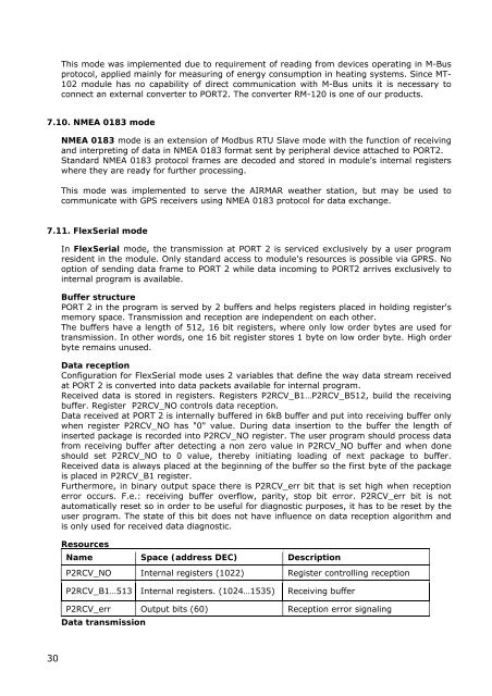
Resources<br />
Name Space (address DEC) Description<br />
P2RCV_NO Internal registers (<strong>102</strong>2) Register controlling reception<br />
P2RCV_B1…513 Internal registers. (<strong>102</strong>4…1535) Receiving buffer<br />
P2RCV_err Output bits (60) Reception error signaling<br />
Data transmission<br />
30


