iDEAl EsPRit - Ideal Heating
iDEAl EsPRit - Ideal Heating
iDEAl EsPRit - Ideal Heating

Create successful ePaper yourself
Turn your PDF publications into a flip-book with our unique Google optimized e-Paper software.
esp8826<br />
Inlet Pressure<br />
Test Point<br />
Esprit - Installation and Servicing<br />
INSTALLATION<br />
30 PRESSURE RELIEF VALVE (PRV) OUTLET - (SAFETY VALVE DRAIN)<br />
The PRV outlet is located at the rear RHS of the boiler service connection area.<br />
Connection of additional pipewok to the PRV outlet should be made prior to connection of CH, DHW and gas connections<br />
for ease of access.<br />
The discharge pipe should be positioned so that the discharge of water or steam cannot create a hazard to the occupants<br />
of the premises or damage the electrical components and wiring.<br />
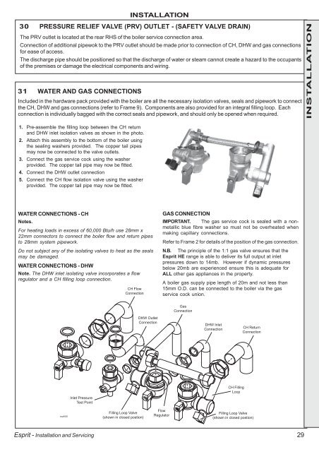
31 WATER AND GAS CONNECTIONS<br />
Included in the hardware pack provided with the boiler are all the necessary isolation valves, seals and pipework to connect<br />
the CH, DHW and gas connections (refer to Frame 9). Components are also provided for an integral filling loop. Each<br />
connection is individually bagged with the correct seals and pipework, and should only be opened when required.<br />
1. Pre-assemble the filling loop between the CH return<br />
and DHW inlet isolation valves as shown in the photo.<br />
2. Attach this assembly to the bottom of the boiler using<br />
the sealing washers provided. The copper tail pipes<br />
may now be connected to the valve outlets.<br />
3. Connect the gas service cock using the washer<br />
provided. The copper tail pipe may now be fitted.<br />
4. Connect the DHW outlet connection<br />
5. Connect the CH flow isolation valve using the washer<br />
provided. The copper tail pipe may now be fitted.<br />
WATER CONNECTIONS - CH<br />
Notes.<br />
For heating loads in excess of 60,000 Btu/h use 28mm x<br />
22mm connectors to connect the boiler flow and return pipes<br />
to 28mm system pipework.<br />
Do not subject any of the isolating valves to heat as the seals<br />
may be damaged.<br />
WATER CONNECTIONS - DHW<br />
Note. The DHW inlet isolating valve incorporates a flow<br />
regulator and a CH filling loop connection.<br />
CH Flow<br />
Connection<br />
Filling Loop Valve<br />
(shown in closed postion)<br />
DHW Outlet<br />
Connection<br />
GAS CONNECTION<br />
IMPORTANT. The gas service cock is sealed with a nonmetallic<br />
blue fibre washer so must not be overheated when<br />
making capillary connections.<br />
Refer to Frame 2 for details of the position of the gas connection.<br />
N.B. The principle of the 1:1 gas valve ensures that the<br />
Esprit HE range is able to deliver its full output at inlet<br />
pressures down to 14mb. However if dynamic pressures<br />
below 20mb are experienced ensure this is adequate for<br />
ALL other gas appliances in the property.<br />
A boiler gas supply pipe length of 20m and not less than<br />
15mm O.D. can be connected to the boiler via the gas<br />
service cock union.<br />
Flow<br />
Regulator<br />
Gas<br />
Connection<br />
DHW Inlet<br />
Connection<br />
CH Filling<br />
Loop<br />
CH Return<br />
Connection<br />
Filling Loop Valve<br />
(shown in closed postion)<br />
29<br />
INSTALLATION