iDEAl EsPRit - Ideal Heating
iDEAl EsPRit - Ideal Heating
iDEAl EsPRit - Ideal Heating

Create successful ePaper yourself
Turn your PDF publications into a flip-book with our unique Google optimized e-Paper software.
Esprit - Installation and Servicing<br />
5<br />
Combustion<br />
chamber<br />
4<br />
Front<br />
SERVICING<br />
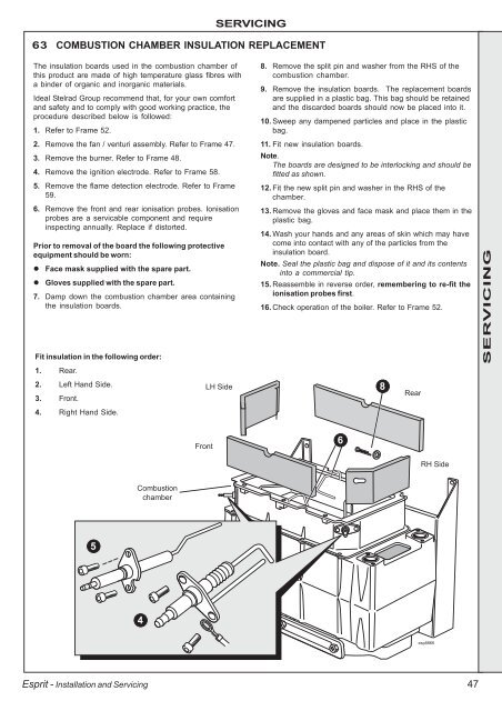
63 COMBUSTION CHAMBER INSULATION REPLACEMENT<br />
The insulation boards used in the combustion chamber of<br />
this product are made of high temperature glass fibres with<br />
a binder of organic and inorganic materials.<br />
<strong>Ideal</strong> Stelrad Group recommend that, for your own comfort<br />
and safety and to comply with good working practice, the<br />
procedure described below is followed:<br />
1. Refer to Frame 52.<br />
2. Remove the fan / venturi assembly. Refer to Frame 47.<br />
3. Remove the burner. Refer to Frame 48.<br />
4. Remove the ignition electrode. Refer to Frame 58.<br />
5. Remove the flame detection electrode. Refer to Frame<br />
59.<br />
6. Remove the front and rear ionisation probes. Ionisation<br />
probes are a servicable component and require<br />
inspecting annually. Replace if distorted.<br />
Prior to removal of the board the following protective<br />
equipment should be worn:<br />
� Face mask supplied with the spare part.<br />
� Gloves supplied with the spare part.<br />
7. Damp down the combustion chamber area containing<br />
the insulation boards.<br />
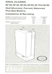
Fit insulation in the following order:<br />
1. Rear.<br />
2. Left Hand Side.<br />
3. Front.<br />
4. Right Hand Side.<br />
LH Side<br />
8. Remove the split pin and washer from the RHS of the<br />
combustion chamber.<br />
9. Remove the insulation boards. The replacement boards<br />
are supplied in a plastic bag. This bag should be retained<br />
and the discarded boards should now be placed into it.<br />
10. Sweep any dampened particles and place in the plastic<br />
bag.<br />
11. Fit new insulation boards.<br />
Note.<br />
The boards are designed to be interlocking and should be<br />
fitted as shown.<br />
12. Fit the new split pin and washer in the RHS of the<br />
chamber.<br />
13. Remove the gloves and face mask and place them in the<br />
plastic bag.<br />
14. Wash your hands and any areas of skin which may have<br />
come into contact with any of the particles from the<br />
insulation board.<br />
Note. Seal the plastic bag and dispose of it and its contents<br />
into a commercial tip.<br />
15. Reassemble in reverse order, remembering to re-fit the<br />
ionisation probes first.<br />
16. Check operation of the boiler. Refer to Frame 52.<br />
6<br />
8<br />
Rear<br />
RH Side<br />
esp8866<br />
47<br />
SERVICING