iDEAl EsPRit - Ideal Heating
iDEAl EsPRit - Ideal Heating
iDEAl EsPRit - Ideal Heating

Create successful ePaper yourself
Turn your PDF publications into a flip-book with our unique Google optimized e-Paper software.
SERVICING<br />
50<br />
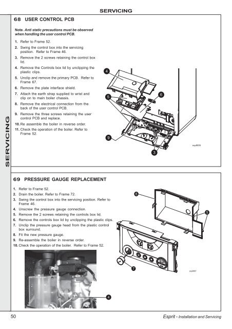
68 USER CONTROL PCB<br />
Note. Anti static precautions must be observed<br />
when handling the user control PCB.<br />
1. Refer to Frame 52.<br />
2. Swing the control box into the servicing<br />
position. Refer to Frame 46.<br />
3. Remove the 2 screws retaining the control box<br />
lid.<br />
4. Remove the Controls box lid by unclipping the<br />
plastic clips.<br />
5. Unclip and remove the primary PCB. Refer to<br />
Frame 67.<br />
6. Remove the plate interface shield.<br />
7. Attach the earth strap supplied to wrist and<br />
clip on to main boiler chassis.<br />
8. Remove the electrical connection from the<br />
back of the user control PCB.<br />
9. Remove the three screws retaining the user<br />
control PCB and replace.<br />
10. Re assemble the boiler in reverse order.<br />
11. Check the operation of the boiler. Refer to<br />
Frame 52.<br />
69 PRESSURE GAUGE REPLACEMENT<br />
1. Refer to Frame 52.<br />
2. Drain the boiler. Refer to Frame 72.<br />
3. Swing the control box into the servicing position. Refer to<br />
Frame 46.<br />
4. Unscrew the pressure gauge connection.<br />
5. Remove the 2 screws retaining the controls box lid.<br />
6. Remove the controls box lid by unclipping the plastic clips.<br />
7. Unclip the pressure gauge head from the plastic control<br />
box surround.<br />
8. Fit the new pressure gauge.<br />
9. Re-assemble the boiler in reverse order.<br />
10. Check the operation of the boiler. Refer to Frame 52.<br />
SERVICING<br />
4<br />
5<br />
9<br />
4<br />
7<br />
6<br />
3<br />
6<br />
esp8855<br />
esp8867<br />
Esprit - Installation and Servicing<br />
5