iDEAl EsPRit - Ideal Heating
iDEAl EsPRit - Ideal Heating
iDEAl EsPRit - Ideal Heating

Create successful ePaper yourself
Turn your PDF publications into a flip-book with our unique Google optimized e-Paper software.
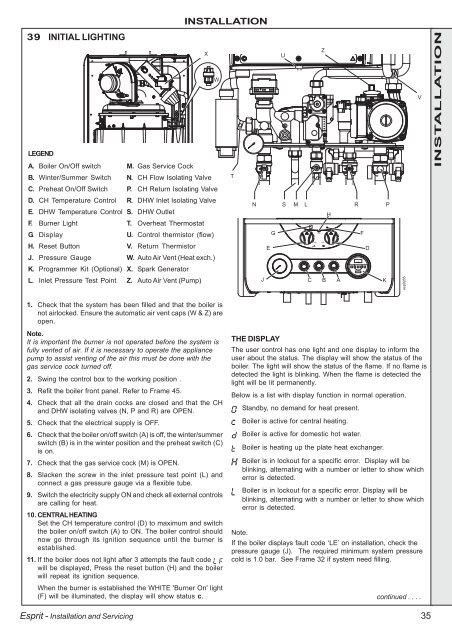
39 INITIAL LIGHTING<br />
LEGEND<br />
A. Boiler On/Off switch M. Gas Service Cock<br />
B. Winter/Summer Switch N. CH Flow Isolating Valve<br />
C. Preheat On/Off Switch P. CH Return Isolating Valve<br />
D. CH Temperature Control R. DHW Inlet Isolating Valve<br />
E. DHW Temperature Control S. DHW Outlet<br />
F. Burner Light<br />
T. Overheat Thermostat<br />
G. Display<br />
U. Control thermistor (flow)<br />
H. Reset Button<br />
V. Return Thermistor<br />
J. Pressure Gauge<br />
W. Auto Air Vent (Heat exch.)<br />
K. Programmer Kit (Optional) X. Spark Generator<br />
L. Inlet Pressure Test Point Z. Auto Air Vent (Pump)<br />
1. Check that the system has been filled and that the boiler is<br />
not airlocked. Ensure the automatic air vent caps (W & Z) are<br />
open.<br />
Note.<br />
It is important the burner is not operated before the system is<br />
fully vented of air. If it is necessary to operate the appliance<br />
pump to assist venting of the air this must be done with the<br />
gas service cock turned off.<br />
2. Swing the control box to the working position .<br />
3. Refit the boiler front panel. Refer to Frame 45.<br />
4. Check that all the drain cocks are closed and that the CH<br />
and DHW isolating valves (N, P and R) are OPEN.<br />
5. Check that the electrical supply is OFF.<br />
6. Check that the boiler on/off switch (A) is off, the winter/summer<br />
switch (B) is in the winter position and the preheat switch (C)<br />
is on.<br />
7. Check that the gas service cock (M) is OPEN.<br />
8. Slacken the screw in the inlet pressure test point (L) and<br />
connect a gas pressure gauge via a flexible tube.<br />
9. Switch the electricity supply ON and check all external controls<br />
are calling for heat.<br />
10. CENTRAL HEATING<br />
Set the CH temperature control (D) to maximum and switch<br />
the boiler on/off switch (A) to ON. The boiler control should<br />
now go through its ignition sequence until the burner is<br />
established.<br />
11. If the boiler does not light after 3 attempts the fault code<br />
will be displayed, Press the reset button (H) and the boiler<br />
will repeat its ignition sequence.<br />
When the burner is established the WHITE 'Burner On' light<br />
(F) will be illuminated, the display will show status c.<br />
Esprit - Installation and Servicing<br />
INSTALLATION<br />
X<br />
W<br />
T<br />
N<br />
E<br />
G<br />
THE DISPLAY<br />
U<br />
S M L R P<br />
min<br />
max<br />
reset<br />
Z<br />
min<br />
preheat on winter boiler on<br />
off summer off<br />
J C B<br />
H<br />
The user control has one light and one display to inform the<br />
user about the status. The display will show the status of the<br />
boiler. The light will show the status of the flame. If no flame is<br />
detected the light is blinking. When the flame is detected the<br />
light will be lit permanently.<br />
Below is a list with display function in normal operation.<br />
Standby, no demand for heat present.<br />
Boiler is active for central heating.<br />
Boiler is active for domestic hot water.<br />
Boiler is heating up the plate heat exchanger.<br />
Boiler is in lockout for a specific error. Display will be<br />
blinking, alternating with a number or letter to show which<br />
error is detected.<br />
Boiler is in lockout for a specific error. Display will be<br />
blinking, alternating with a number or letter to show which<br />
error is detected.<br />
Note.<br />
If the boiler displays fault code ‘LE’ on installation, check the<br />
pressure gauge (J). The required minimum system pressure<br />
cold is 1.0 bar. See Frame 32 if system need filling.<br />
max<br />
A<br />
F<br />
D<br />
K<br />
esp9265<br />
V<br />
continued . . . .<br />
35<br />
INSTALLATION