GAS SUPPLY The local gas supplier should be consulted, at the installation planning stage, in order to establish the availability of an adequate supply of gas. An existing service pipe must NOT be used without prior consultation with the local gas supplier. The boiler MUST be installed on a gas supply with a governed meter only. A gas meter can only be connected by the local gas supplier or by a CORGI registered engineer. In IE by a competent person. An existing meter should be checked, preferably by the gas supplier, to ensure that the meter is adequate to deal with the rate of gas supply required. N.B. The principle of the 1:1 gas valve ensures that the Esprit HE range is able to deliver it’s full output at inlet pressures down to 14mb. However if dynamic pressures below 20mb are experienced ensure this is adequate for ALL other gas appliances in the property. IMPORTANT. Installation pipes must be fitted in accordance with BS.6891. In IE refer to IS.813:2002. Pipework from the meter to the boiler MUST be of an adequate size, i.e. no longer than 20m and not less than 15mm O.D. The complete installation MUST be tested for gas soundness and purged as described in the above code. FLUE INSTALLATION Pluming will occur at the terminal so terminal positions where this could cause a nuisance should be avoided. The flue must be installed in accordance with the recommendations of BS. 5440-1: 2000. In IE refer to I.S. 813:2002. The following notes are intended for general guidance: 1. The boiler MUST be installed so that the terminal is exposed to external air. 2. It is important that the position of the terminal allows the free passage of air across it at all times. 3. Minimum acceptable spacing from the terminal to obstructions and ventilation openings are specified in Table 4. 4. Where the lowest part of the terminal is fitted less than 2m (6'6") above a balcony, above ground or above a flat roof to which people have access then the terminal MUST be protected by a purpose designed guard. Terminal guards are available from boiler suppliers. (Ask for TFC flue guard model no. K6 - round, plastic coated). In case of difficulty contact: Grasslin (UK) Ltd. Tel. + 44 (0) 01732 359 888 Tower House, Vale Rise Fax. + 44 (0) 01732 354 445 Tonbridge. Kent TN9 1TB www.tfc-group.co.uk Ensure that the guard is fitted centrally. 5. The flue assembly shall be so placed or shielded as to prevent ignition or damage to any part of any building. 6. The air inlet/products outlet duct and the terminal of the boiler MUST NOT be closer than 25mm (1") to combustible material. Detailed recommendations on the protection of combustible material are given in BS. 5440-1:2000. GENERAL Table 4 - Balanced Flue Terminal Position Flue Terminal Positions Min. Spacing* 1. Directly below, above or alongside an opening window, air vent or other ventilation opening. 300mm (12") 2. Below guttering, drain pipes or soil pipes. 25mm ( 1")* BS5440-1 2000 75mm (3") 3. Below eaves. 25mm (1")* BS5440-1 2000 200mm (8") 4. Below balconies or a car port roof. 25mm (1")* BS5440-1 2000 200mm (8") 5. From vertical drain pipes or soil pipes. 25mm (1")* BS5440-1 2000 150mm (6") 6. From an internal or external corner or to a 25mm (1")* boundary along side the terminal. BS5440-1 2000 300mm (12") 7. Above adjacent ground, roof or balcony level. 300mm (12") 8. From a surface or a boundary facing the terminal. 600mm (24") 9. From a terminal facing a terminal. 1,200mm (48") 10. From an opening in a car port (e.g. door or window) into dwelling. 1,200mm (48") 11. Vertically from a terminal on the same wall. 1,500mm (60") 12. Horizontally from a terminal on the wall. Vertical Terminals 300mm (12") 13. Above the roof pitch with roof slope of all angles. 300mm (12") Above flat roof. 300mm (12") 14. From a single wall face. 300mm (12") From corner walls. 300mm (12") * Only one reduction down to 25mm is allowable per installation otherwise BS5440-1 2000 dimensions must be followed. IMPORTANT. It is absolutely essential to ensure, in practice, that products of combustion discharging from the terminal cannot re-enter the building or any other adjacent building through ventilators, windows, doors, other sources of natural air infiltration, or forced ventilation / air conditioning. If this should occur the appliance MUST be turned OFF, labelled as 'unsafe' until corrective action can be taken. TERMINAL The terminal assembly can be adapted to accommodate various wall thicknesses. Refer to Frame 10 . AIR SUPPLY It is NOT necessary to have a purpose-provided air vent in the room or internal space in which the boiler is installed. Neither is it necessary to ventilate a cupboard or compartment in which the boiler is installed, due to the low surface temperatures of the boiler casing during operation; therefore the requirements of BS 6798, Clause 12, and BS 5440:2 may be disregarded. WATER CIRCULATION SYSTEM IMPORTANT. A minimum length of 1 metre of copper pipe MUST be fitted to both flow and return connections from the boiler before connection to any plastic piping. The central heating system should be in accordance with BS.6798 and, in addition, for smallbore and microbore systems, BS.5449. WATER TREATMENT - see Frame 6 8 Esprit - Installation and Servicing
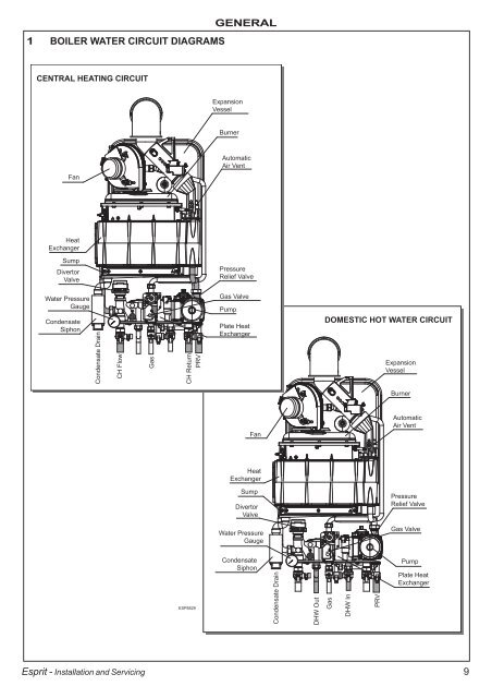
1 BOILER WATER CIRCUIT DIAGRAMS CENTRAL HEATING CIRCUIT Fan Heat Exchanger Sump Divertor Valve Water Pressure Gauge Condensate Siphon Condensate Drain CH Flow Esprit - Installation and Servicing Gas CH Return PRV ESP8829 GENERAL Expansion Vessel Burner Automatic Air Vent Pressure Relief Valve Gas Valve Pump Plate Heat Exchanger Fan Heat Exchanger Sump Divertor Valve Water Pressure Gauge Condensate Siphon Condensate Drain DHW Out DOMESTIC HOT WATER CIRCUIT Gas DHW In PRV Expansion Vessel Burner Automatic Air Vent Pressure Relief Valve Gas Valve Pump Plate Heat Exchanger 9