iDEAl EsPRit - Ideal Heating
iDEAl EsPRit - Ideal Heating
iDEAl EsPRit - Ideal Heating
Create successful ePaper yourself
Turn your PDF publications into a flip-book with our unique Google optimized e-Paper software.
GAS SUPPLY<br />
The local gas supplier should be consulted, at the installation<br />
planning stage, in order to establish the availability of an<br />
adequate supply of gas. An existing service pipe must NOT be<br />
used without prior consultation with the local gas supplier.<br />
The boiler MUST be installed on a gas supply with a governed<br />
meter only.<br />
A gas meter can only be connected by the local gas supplier or<br />
by a CORGI registered engineer. In IE by a competent person.<br />
An existing meter should be checked, preferably by the gas<br />
supplier, to ensure that the meter is adequate to deal with the<br />
rate of gas supply required.<br />
N.B. The principle of the 1:1 gas valve ensures that the Esprit<br />
HE range is able to deliver it’s full output at inlet pressures<br />
down to 14mb. However if dynamic pressures below 20mb are<br />
experienced ensure this is adequate for ALL other gas<br />
appliances in the property.<br />
IMPORTANT.<br />
Installation pipes must be fitted in accordance with BS.6891. In<br />
IE refer to IS.813:2002. Pipework from the meter to the boiler<br />
MUST be of an adequate size, i.e. no longer than 20m and not<br />
less than 15mm O.D.<br />
The complete installation MUST be tested for gas soundness<br />
and purged as described in the above code.<br />
FLUE INSTALLATION<br />
Pluming will occur at the terminal so terminal positions where<br />
this could cause a nuisance should be avoided.<br />
The flue must be installed in accordance with the<br />
recommendations of BS. 5440-1: 2000.<br />
In IE refer to I.S. 813:2002.<br />
The following notes are intended for general guidance:<br />
1. The boiler MUST be installed so that the terminal is exposed<br />
to external air.<br />
2. It is important that the position of the terminal allows the free<br />
passage of air across it at all times.<br />
3. Minimum acceptable spacing from the terminal to<br />
obstructions and ventilation openings are specified in<br />
Table 4.<br />
4. Where the lowest part of the terminal is fitted less than 2m<br />
(6'6") above a balcony, above ground or above a flat roof to<br />
which people have access then the terminal MUST be<br />
protected by a purpose designed guard.<br />
Terminal guards are available from boiler suppliers. (Ask for<br />
TFC flue guard model no. K6 - round, plastic coated). In case<br />
of difficulty contact:<br />
Grasslin (UK) Ltd. Tel. + 44 (0) 01732 359 888<br />
Tower House, Vale Rise Fax. + 44 (0) 01732 354 445<br />
Tonbridge. Kent TN9 1TB www.tfc-group.co.uk<br />
Ensure that the guard is fitted centrally.<br />
5. The flue assembly shall be so placed or shielded as to<br />
prevent ignition or damage to any part of any building.<br />
6. The air inlet/products outlet duct and the terminal of the<br />
boiler MUST NOT be closer than 25mm (1") to combustible<br />
material. Detailed recommendations on the protection of<br />
combustible material are given in BS. 5440-1:2000.<br />
GENERAL<br />
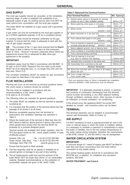
Table 4 - Balanced Flue Terminal Position<br />
Flue Terminal Positions Min. Spacing*<br />
1. Directly below, above or alongside an opening<br />
window, air vent or other ventilation opening. 300mm (12")<br />
2. Below guttering, drain pipes or soil pipes. 25mm ( 1")*<br />
BS5440-1 2000 75mm (3")<br />
3. Below eaves. 25mm (1")*<br />
BS5440-1 2000 200mm (8")<br />
4. Below balconies or a car port roof. 25mm (1")*<br />
BS5440-1 2000 200mm (8")<br />
5. From vertical drain pipes or soil pipes. 25mm (1")*<br />
BS5440-1 2000 150mm (6")<br />
6. From an internal or external corner or to a 25mm (1")*<br />
boundary along side the terminal. BS5440-1 2000 300mm (12")<br />
7. Above adjacent ground, roof or balcony level. 300mm (12")<br />
8. From a surface or a boundary facing the terminal. 600mm (24")<br />
9. From a terminal facing a terminal. 1,200mm (48")<br />
10. From an opening in a car port<br />
(e.g. door or window) into dwelling. 1,200mm (48")<br />
11. Vertically from a terminal on the same wall. 1,500mm (60")<br />
12. Horizontally from a terminal on the wall.<br />
Vertical Terminals<br />
300mm (12")<br />
13. Above the roof pitch with roof slope of all angles. 300mm (12")<br />
Above flat roof. 300mm (12")<br />
14. From a single wall face. 300mm (12")<br />
From corner walls. 300mm (12")<br />
* Only one reduction down to 25mm is allowable per installation<br />
otherwise BS5440-1 2000 dimensions must be followed.<br />
IMPORTANT. It is absolutely essential to ensure, in practice,<br />
that products of combustion discharging from the terminal<br />
cannot re-enter the building or any other adjacent building<br />
through ventilators, windows, doors, other sources of natural<br />
air infiltration, or forced ventilation / air conditioning.<br />
If this should occur the appliance MUST be turned OFF,<br />
labelled as 'unsafe' until corrective action can be taken.<br />
TERMINAL<br />
The terminal assembly can be adapted to accommodate<br />
various wall thicknesses. Refer to Frame 10 .<br />
AIR SUPPLY<br />
It is NOT necessary to have a purpose-provided air vent in the<br />
room or internal space in which the boiler is installed. Neither<br />
is it necessary to ventilate a cupboard or compartment in which<br />
the boiler is installed, due to the low surface temperatures of<br />
the boiler casing during operation; therefore the requirements<br />
of BS 6798, Clause 12, and BS 5440:2 may be disregarded.<br />
WATER CIRCULATION SYSTEM<br />
IMPORTANT.<br />
A minimum length of 1 metre of copper pipe MUST be fitted to<br />
both flow and return connections from the boiler before<br />
connection to any plastic piping.<br />
The central heating system should be in accordance with<br />
BS.6798 and, in addition, for smallbore and microbore<br />
systems, BS.5449.<br />
WATER TREATMENT - see Frame 6<br />
8 Esprit - Installation and Servicing


