INFORMATION & REQUIREMENTS ELECTRIC SERVICE - NStar
INFORMATION & REQUIREMENTS ELECTRIC SERVICE - NStar
INFORMATION & REQUIREMENTS ELECTRIC SERVICE - NStar

Create successful ePaper yourself
Turn your PDF publications into a flip-book with our unique Google optimized e-Paper software.
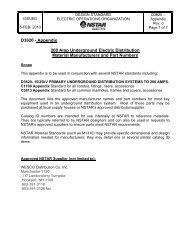
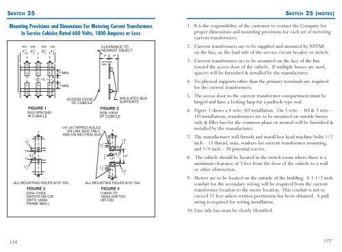
SKETCH 25<br />
Mounting Provisions and Dimensions For Metering Current Transformers<br />
In Service Cubicles Rated 600 Volts, 1800 Amperes or Less<br />
MIN. MIN. MIN. MIN.<br />
4 1"<br />
8 1" 8 1" 4 1"<br />
2 2 2 2<br />
CLEARANCE TO<br />
NEAREST OBJECT<br />
FIGURE 1 FIGURE 2<br />
BUS SPACING<br />
SIDE VIEW<br />
IN CUBICLE<br />
OF CUBICLE<br />
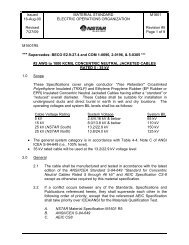
1 1"<br />
2<br />
1"<br />
1"<br />
5 7"<br />
8<br />
SEE FIG. 3 & 4<br />
7"MIN.<br />
7"MIN.<br />
1/4"-20 TAPPED HOLES<br />
ON LINE SIDE ONLY,<br />
AND ON NEUTRAL BUS<br />
11"<br />
2<br />
1 1"<br />
1"<br />
2<br />
1<br />
2<br />
ALL MOUNTING HOLES 9/16" DIA.<br />
ACCESS DOOR<br />
OF CUBICLE<br />
7"<br />
APPROX.<br />
MIN.<br />
7"<br />
8 1"<br />
2<br />
INSULATED BUS<br />
SUPPORTS<br />
1 3"<br />
4<br />
10"<br />
1 3"<br />
4<br />
ALL MOUNTING HOLES 9/16" DIA.<br />
FIGURE 3 FIGURE 4<br />
225A-1200A<br />
(1400A TO<br />
SWITCH OR C/B<br />
1800A SWITCH<br />
(WITH 1200A<br />
OR C/B)<br />
FRAME MAX.)<br />
7"<br />
8<br />
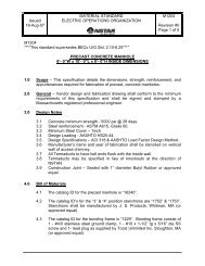
SKETCH 25 (NOTES)<br />
1. It is the responsibility of the customer to contact the Company for<br />
proper dimensions and mounting provisions for each set of metering<br />
current transformers.<br />
2. Current transformers are to be supplied and mounted by NSTAR<br />
on the bus, on the load side of the service circuit breaker or switch.<br />
3. Current transformers are to be mounted on the face of the bus<br />
toward the access door of the cubicle. If multiple busses are used,<br />
spacers will be furnished & installed by the manufacturer.<br />
4. No physical supports other than the primary terminals are required<br />
for the current transformers.<br />
5. The access door to the current transformer compartment must be<br />
hinged and have a locking hasp for a padlock type seal.<br />
6. Figure 1 shows a 4 wire-3Ø installation. On 3 wire – 3Ø & 3 wire –<br />
1Ø installations, transformers are to be mounted on outside busses<br />
only & filler bus for the common phase or neutral will be furnished &<br />
installed by the manufacturer.<br />
7. The manufacturer will furnish and install hex head machine bolts 1/2<br />
inch – 13 thread, nuts, washers for current transformer mounting,<br />
and 1/4 inch – 20 potential screws.<br />
8. The cubicle should be located in the switch room where there is a<br />
minimum clearance of 3 feet from the door of the cubicle to a wall<br />
or other obstruction.<br />
9. Meters are to be located on the outside of the building. A 1-1/2 inch<br />
conduit for the secondary wiring will be required from the current<br />
transformer location to the meter location. This conduit is not to<br />
exceed 25 feet unless written permission has been obtained. A pull<br />
string is required for wiring installation.<br />
10.Line side bus must be clearly identified.<br />
134<br />
135