
You also want an ePaper? Increase the reach of your titles
YUMPU automatically turns print PDFs into web optimized ePapers that Google loves.
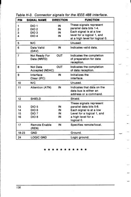
Table H-3. Connector signals for the IEEE-488 interface.<br />
PIN SIGNAL NAME DIRECTION FUNCTION<br />
1 DIO 1 IN These signals represent<br />
2 DIO 2 IN parallel data bits 1-4.<br />
3 DIO 3 IN Each signal is at a low<br />
4 DIO 4 IN level for a logical 1, and<br />
at a high level for logical 0.<br />
5 N/C Unused.<br />
6 Data Valid IN Indicates valid data.<br />
(DA’4<br />
7 Not Ready For OUT Indicates the completion<br />
Data (NRFD) of preparation for data<br />
reception.<br />
6 Not Data OUT Indicates the completion<br />
Accepted (NDAC)<br />
of data reception.<br />
9 Interface IN Initializes the<br />
Clear (IFC)<br />
interface.<br />
<strong>10</strong> N/C Unused.<br />
11 Attention (ATN) IN Indicates that d&a on the<br />
data bus is either an<br />
address or a command.<br />
12 SHIELD Shield.<br />
These signals represent<br />
13 DIO 5 IN parallel data bits 5-8.<br />
14 DIO 6 IN Each signal is at a low<br />
15 DIO 7 IN Level for a logical 1, and<br />
16 DIO 8 IN a high level for a<br />
logical 0.<br />
17 Remote Enable IN Specifies remote/local.<br />
(REV<br />
18-23 GND Ground.<br />
24 LOGIC GND Logic ground.<br />
-.<br />
-<br />
-<br />
***********<br />
136