Hardware Interface Description - KORE Telematics
Hardware Interface Description - KORE Telematics
Hardware Interface Description - KORE Telematics
Create successful ePaper yourself
Turn your PDF publications into a flip-book with our unique Google optimized e-Paper software.
XT55/56 <strong>Hardware</strong> <strong>Interface</strong> <strong>Description</strong><br />
Confidential / Released<br />
s<br />
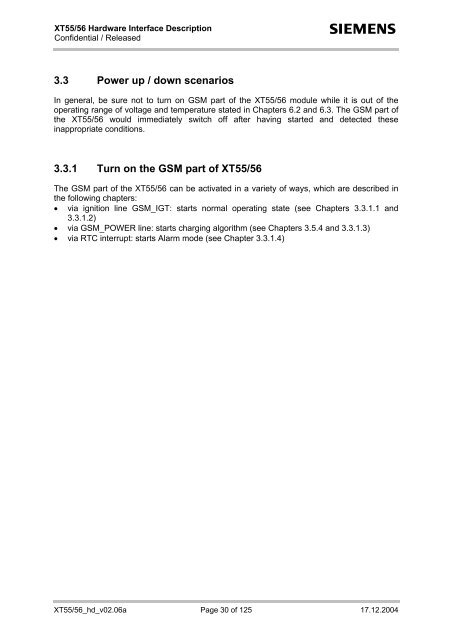
3.3 Power up / down scenarios<br />
In general, be sure not to turn on GSM part of the XT55/56 module while it is out of the<br />
operating range of voltage and temperature stated in Chapters 6.2 and 6.3. The GSM part of<br />
the XT55/56 would immediately switch off after having started and detected these<br />
inappropriate conditions.<br />
3.3.1 Turn on the GSM part of XT55/56<br />
The GSM part of the XT55/56 can be activated in a variety of ways, which are described in<br />
the following chapters:<br />
• via ignition line GSM_IGT: starts normal operating state (see Chapters 3.3.1.1 and<br />
3.3.1.2)<br />
• via GSM_POWER line: starts charging algorithm (see Chapters 3.5.4 and 3.3.1.3)<br />
• via RTC interrupt: starts Alarm mode (see Chapter 3.3.1.4)<br />
XT55/56_hd_v02.06a Page 30 of 125 17.12.2004


