

Hardware Interface Description - KORE Telematics
Hardware Interface Description - KORE Telematics
Hardware Interface Description - KORE Telematics

You also want an ePaper? Increase the reach of your titles
YUMPU automatically turns print PDFs into web optimized ePapers that Google loves.
XT55/56 <strong>Hardware</strong> <strong>Interface</strong> <strong>Description</strong><br />
Confidential / Released<br />
s<br />
The U.FL-R-SMT connector has been chosen as antenna reference point (ARP) for the<br />
Siemens reference equipment submitted to type approve XT55/56. All RF data specified<br />
throughout this manual are related to the ARP. For compliance with the test results of the<br />
Siemens type approval you are advised to give priority to the connector, rather than using the<br />
antenna pad.<br />
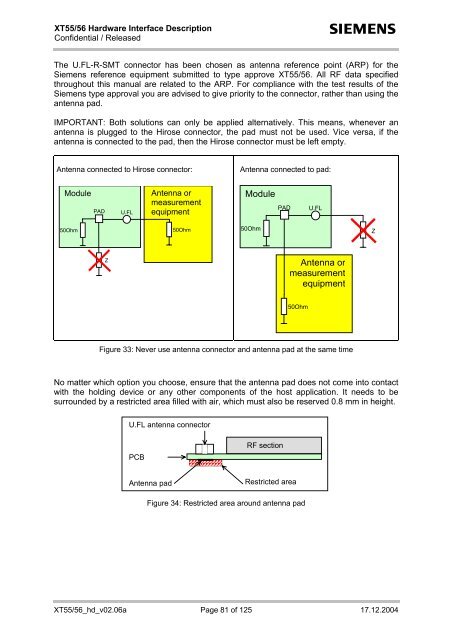
IMPORTANT: Both solutions can only be applied alternatively. This means, whenever an<br />
antenna is plugged to the Hirose connector, the pad must not be used. Vice versa, if the<br />
antenna is connected to the pad, then the Hirose connector must be left empty.<br />
Antenna connected to Hirose connector:<br />
Antenna connected to pad:<br />
Module<br />
PAD<br />
U.FL<br />
Antenna or<br />
measurement<br />
equipment<br />
Module<br />
PAD<br />
U.FL<br />
50Ohm<br />
50Ohm<br />
50Ohm<br />
Z<br />
Z<br />
Antenna or<br />
measurement<br />
equipment<br />
50Ohm<br />
Figure 33: Never use antenna connector and antenna pad at the same time<br />
No matter which option you choose, ensure that the antenna pad does not come into contact<br />
with the holding device or any other components of the host application. It needs to be<br />
surrounded by a restricted area filled with air, which must also be reserved 0.8 mm in height.<br />
U.FL antenna connector<br />
PCB<br />
RF section<br />
Antenna pad<br />
Restricted area<br />
Figure 34: Restricted area around antenna pad<br />
XT55/56_hd_v02.06a Page 81 of 125 17.12.2004


