

Hardware Interface Description - KORE Telematics
Hardware Interface Description - KORE Telematics
Hardware Interface Description - KORE Telematics

Create successful ePaper yourself
Turn your PDF publications into a flip-book with our unique Google optimized e-Paper software.
XT55/56 <strong>Hardware</strong> <strong>Interface</strong> <strong>Description</strong><br />
Confidential / Released<br />
s<br />
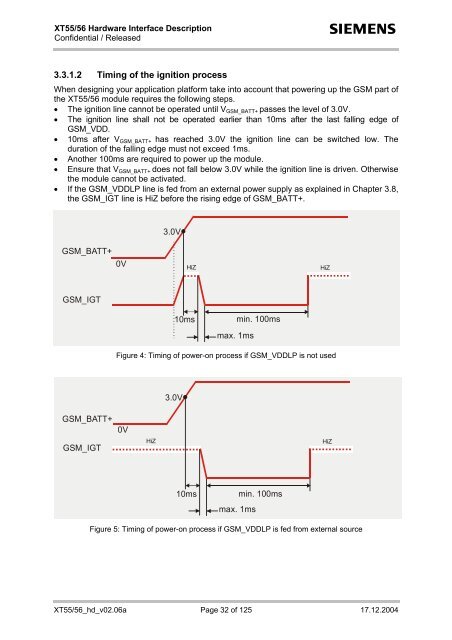
3.3.1.2 Timing of the ignition process<br />
When designing your application platform take into account that powering up the GSM part of<br />
the XT55/56 module requires the following steps.<br />
• The ignition line cannot be operated until V GSM_BATT+ passes the level of 3.0V.<br />
• The ignition line shall not be operated earlier than 10ms after the last falling edge of<br />
GSM_VDD.<br />
• 10ms after V GSM_BATT+ has reached 3.0V the ignition line can be switched low. The<br />
duration of the falling edge must not exceed 1ms.<br />
• Another 100ms are required to power up the module.<br />
• Ensure that V GSM_BATT+ does not fall below 3.0V while the ignition line is driven. Otherwise<br />
the module cannot be activated.<br />
• If the GSM_VDDLP line is fed from an external power supply as explained in Chapter 3.8,<br />
the GSM_IGT line is HiZ before the rising edge of GSM_BATT+.<br />
3.0V<br />
GSM_BATT+<br />
0V<br />
HiZ<br />
HiZ<br />
GSM_IGT<br />
10ms<br />
min. 100ms<br />
max. 1ms<br />
Figure 4: Timing of power-on process if GSM_VDDLP is not used<br />
3.0V<br />
GSM_BATT+<br />
GSM_IGT<br />
0V<br />
HiZ<br />
HiZ<br />
10ms<br />
max. 1ms<br />
min. 100ms<br />
Figure 5: Timing of power-on process if GSM_VDDLP is fed from external source<br />
XT55/56_hd_v02.06a Page 32 of 125 17.12.2004


