

Hardware Interface Description - KORE Telematics
Hardware Interface Description - KORE Telematics
Hardware Interface Description - KORE Telematics

You also want an ePaper? Increase the reach of your titles
YUMPU automatically turns print PDFs into web optimized ePapers that Google loves.
XT55/56 <strong>Hardware</strong> <strong>Interface</strong> <strong>Description</strong><br />
Confidential / Released<br />
s<br />
3.11 SIM interface<br />
The baseband processor has an integrated SIM interface compatible with the ISO 7816 IC<br />
Card standard. This is wired to the host interface (board-to-board connector) in order to be<br />
connected to an external SIM card holder. Six pins on the board-to-board connector are<br />
reserved for the SIM interface.<br />
The GSM_CCIN pin serves to detect whether a tray (with SIM card) is present in the card<br />
holder. Using the GSM_CCIN pin is mandatory for compliance with the GSM 11.11<br />
recommendation if the mechanical design of the host application allows the user to remove<br />
the SIM card during operation. See Chapter 3.11.1 for details.<br />
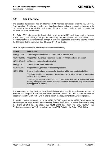
Table 15: Signals of the SIM interface (board-to-board connector)<br />
Signal<br />
GSM_CCGND<br />
GSM_CCCLK<br />
GSM_CCVCC<br />
GSM_CCIO<br />
GSM_CCRST<br />
GSM_CCIN<br />
<strong>Description</strong><br />
Separate ground connection for SIM card to improve EMC.<br />
Chipcard clock, various clock rates can be set in the baseband processor.<br />
SIM supply voltage from PSU-ASIC<br />
Serial data line, input and output.<br />
Chipcard reset, provided by baseband processor.<br />
Input on the baseband processor for detecting a SIM card tray in the holder.<br />
The GSM_CCIN pin is mandatory for applications that allow the user to remove the<br />
SIM card during operation.<br />
The GSM_CCIN pin is solely intended for use with a SIM card. It must not be used<br />
for any other purposes. Failure to comply with this requirement may invalidate the<br />
type approval of XT55/56.<br />
It is recommended that the total cable length between the board-to-board connector pins on<br />
XT55/56 and the pins of the SIM card holder does not exceed 200 mm in order to meet the<br />
specifications of 3GPP TS 51.010-1 and to satisfy the requirements of EMC compliance.<br />
To avoid possible cross-talk from the GSM_CCCLK signal to the GSM_CCIO signal be<br />
careful that both lines are not placed closely next to each other. A useful approach is using<br />
the GSM_CCGND line to shield the GSM_CCIO line from the GSM_CCCLK line.<br />
Furthermore connect a 47 pF capacitor from the GSM_CCIO to the GSM_CCGND line.<br />
XT55/56_hd_v02.06a Page 61 of 125 17.12.2004


