Hardware Interface Description - KORE Telematics
Hardware Interface Description - KORE Telematics
Hardware Interface Description - KORE Telematics
Create successful ePaper yourself
Turn your PDF publications into a flip-book with our unique Google optimized e-Paper software.
XT55/56 <strong>Hardware</strong> <strong>Interface</strong> <strong>Description</strong><br />
Confidential / Released<br />
s<br />
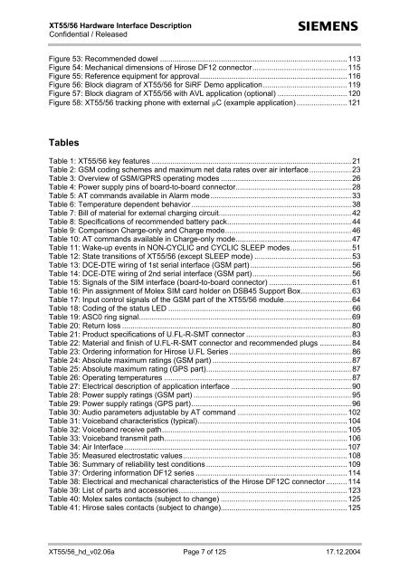
Figure 53: Recommended dowel .........................................................................................113<br />
Figure 54: Mechanical dimensions of Hirose DF12 connector.............................................115<br />
Figure 55: Reference equipment for approval......................................................................116<br />
Figure 56: Block diagram of XT55/56 for SiRF Demo application........................................119<br />
Figure 57: Block diagram of XT55/56 with AVL application (optional) .................................120<br />
Figure 58: XT55/56 tracking phone with external µC (example application) ........................121<br />
Tables<br />
Table 1: XT55/56 key features ...............................................................................................21<br />
Table 2: GSM coding schemes and maximum net data rates over air interface....................23<br />
Table 3: Overview of GSM/GPRS operating modes ..............................................................26<br />
Table 4: Power supply pins of board-to-board connector.......................................................28<br />
Table 5: AT commands available in Alarm mode...................................................................33<br />
Table 6: Temperature dependent behavior ............................................................................38<br />
Table 7: Bill of material for external charging circuit...............................................................42<br />
Table 8: Specifications of recommended battery pack...........................................................44<br />
Table 9: Comparison Charge-only and Charge mode............................................................46<br />
Table 10: AT commands available in Charge-only mode.......................................................47<br />
Table 11: Wake-up events in NON-CYCLIC and CYCLIC SLEEP modes.............................51<br />
Table 12: State transitions of XT55/56 (except SLEEP mode) ..............................................53<br />
Table 13: DCE-DTE wiring of 1st serial interface (GSM part) ................................................56<br />
Table 14: DCE-DTE wiring of 2nd serial interface (GSM part)...............................................56<br />
Table 15: Signals of the SIM interface (board-to-board connector) .......................................61<br />
Table 16: Pin assignment of Molex SIM card holder on DSB45 Support Box........................63<br />
Table 17: Input control signals of the GSM part of the XT55/56 module................................64<br />
Table 18: Coding of the status LED .......................................................................................66<br />
Table 19: ASC0 ring signal.....................................................................................................69<br />
Table 20: Return loss .............................................................................................................80<br />
Table 21: Product specifications of U.FL-R-SMT connector ..................................................83<br />
Table 22: Material and finish of U.FL-R-SMT connector and recommended plugs ...............84<br />
Table 23: Ordering information for Hirose U.FL Series ..........................................................86<br />
Table 24: Absolute maximum ratings (GSM part) ..................................................................87<br />
Table 25: Absolute maximum rating (GPS part).....................................................................87<br />
Table 26: Operating temperatures .........................................................................................87<br />
Table 27: Electrical description of application interface .........................................................90<br />
Table 28: Power supply ratings (GSM part) ...........................................................................95<br />
Table 29: Power supply ratings (GPS part)............................................................................96<br />
Table 30: Audio parameters adjustable by AT command ....................................................102<br />
Table 31: Voiceband characteristics (typical).......................................................................104<br />
Table 32: Voiceband receive path........................................................................................105<br />
Table 33: Voiceband transmit path.......................................................................................106<br />
Table 34: Air <strong>Interface</strong>..........................................................................................................107<br />
Table 35: Measured electrostatic values..............................................................................108<br />
Table 36: Summary of reliability test conditions ...................................................................109<br />
Table 37: Ordering information DF12 series ........................................................................114<br />
Table 38: Electrical and mechanical characteristics of the Hirose DF12C connector..........114<br />
Table 39: List of parts and accessories................................................................................123<br />
Table 40: Molex sales contacts (subject to change) ............................................................125<br />
Table 41: Hirose sales contacts (subject to change)............................................................125<br />
XT55/56_hd_v02.06a Page 7 of 125 17.12.2004


