

Hardware Interface Description - KORE Telematics
Hardware Interface Description - KORE Telematics
Hardware Interface Description - KORE Telematics

You also want an ePaper? Increase the reach of your titles
YUMPU automatically turns print PDFs into web optimized ePapers that Google loves.
XT55/56 <strong>Hardware</strong> <strong>Interface</strong> <strong>Description</strong><br />
Confidential / Released<br />
s<br />
Note:<br />
Do not connect the charger to the GSM_BATT+ lines. Only the charger input of the<br />
external charging circuit is intended as input for charging current! The<br />
GSM_POWER pin of XT55/56 is the input only for indicating a connected charger!<br />
The battery manufacturer must guarantee that the battery complies with the<br />
described charging technique.<br />
What to do if software controlled charging does not start up<br />
If trickle charging fails to raise the battery voltage to 3.2V within 60 minutes +10%, processor<br />
controlled charging does not begin. To start fast charging you can do one of the following:<br />
• Once the voltage has risen above its minimum of 3V, you can try to start software<br />
controlled charging by pulling the GSM_IGT line to ground.<br />
• If the voltage is still below 3V, driving the GSM_IGT line to ground switches the timer off.<br />
Without the timer running, the GSM part of the XT55/56 module will not proceed to<br />
software controlled charging. To restart the timer you are required to shortly disconnect<br />
and reconnect the charger.<br />
3.5.4 Operating modes during charging<br />
Of course, the battery can be charged regardless of the engine's operating mode. When the<br />
GSM engine is in Normal mode (SLEEP, IDLE, TALK, GPRS IDLE or GPRS DATA mode), it<br />
remains operational while charging is in progress (provided that sufficient voltage is applied).<br />
The charging process during the Normal mode is referred to as Charge mode.<br />
If the charger is connected to the charger input of the external charging circuit and the<br />
module’s GSM_POWER pin while GSM part of XT55/56 is in POWER DOWN mode, the<br />
GSM part of the XT55/56 goes into Charge-only mode.<br />
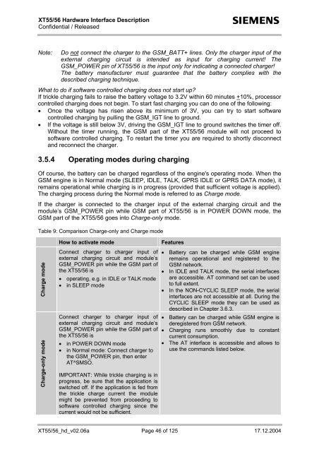
Table 9: Comparison Charge-only and Charge mode<br />
Charge mode<br />
Charge-only mode<br />
How to activate mode<br />
Connect charger to charger input of<br />
external charging circuit and module’s<br />
GSM_POWER pin while the GSM part of<br />
the XT55/56 is<br />
• operating, e.g. in IDLE or TALK mode<br />
• in SLEEP mode<br />
Connect charger to charger input of<br />
external charging circuit and module’s<br />
GSM_POWER pin while the GSM part of<br />
the XT55/56 is<br />
• in POWER DOWN mode<br />
• in Normal mode: Connect charger to<br />
the GSM_POWER pin, then enter<br />
AT^SMSO.<br />
IMPORTANT: While trickle charging is in<br />
progress, be sure that the application is<br />
switched off. If the application is fed from<br />
the trickle charge current the module<br />
might be prevented from proceeding to<br />
software controlled charging since the<br />
current would not be sufficient.<br />
Features<br />
• Battery can be charged while GSM engine<br />
remains operational and registered to the<br />
GSM network.<br />
• In IDLE and TALK mode, the serial interfaces<br />
are accessible. AT command set can be used<br />
to full extent.<br />
• In the NON-CYCLIC SLEEP mode, the serial<br />
interfaces are not accessible at all. During the<br />
CYCLIC SLEEP mode they can be used as<br />
described in Chapter 3.6.3.<br />
• Battery can be charged while GSM engine is<br />
deregistered from GSM network.<br />
• Charging runs smoothly due to constant<br />
current consumption.<br />
• The AT interface is accessible and allows to<br />
use the commands listed below.<br />
XT55/56_hd_v02.06a Page 46 of 125 17.12.2004


