ÐаÑалог Weidmuller: Electronics - Analogue Signal Conditioning
ÐаÑалог Weidmuller: Electronics - Analogue Signal Conditioning
ÐаÑалог Weidmuller: Electronics - Analogue Signal Conditioning

Create successful ePaper yourself
Turn your PDF publications into a flip-book with our unique Google optimized e-Paper software.
Technical data<br />
Technical appendix/Glossary<br />
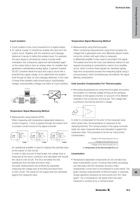
3-port Isolation<br />
Temperature <strong>Signal</strong> Measuring Method<br />
• 3-port isolation is the most universal form of signal isolator<br />
• An optical coupler or transformer isolates the input from the<br />
output circuit. Together with the clearance and creepage<br />
distances it serves to define the isolation level. For example,<br />
the input signal is converted by means of pulse-width<br />
modulation into a frequency signal and demodulated again<br />
on the output side to form an analog value. An amplifier then<br />
generates a standardised analog signal. A galvanic isolated<br />
DC/DC converter feeds the input and output circuit with a<br />
potential free supply voltage. It too determines the isolation<br />
level through its data, air and creepage distances. In the case<br />
of these three isolation paths (input/output, input/auxiliary<br />
voltage, output/auxiliary voltage) one refers to 3-port isolation.<br />
• Measurements using thermocouples<br />
When conducting measurements using thermocouples the<br />
voltage that is generated when two differently alloyed metals<br />
come into contact with each other is measured.<br />
A differential amplifier is then used to recondition the signal.<br />
The easiest (and thus the most cost effective) method of sub<br />
sequent processing is conducted by means of an amplifier<br />
circuit, which converts these signals into standard signals.<br />
High-end components process the measuring signal using a<br />
microprocessor, which simultaneously reconditions the signal<br />
(filtering, linearisation)<br />
Cold Junction Compensation For Thermocouples<br />
• Recording temperatures by using thermocouples encounters<br />
the problem of a thermal voltage forming at the clamping<br />
terminals on the signal converter on account of the different<br />
materials in the conductors and bus bar. This voltage then<br />
counteracts the thermal element‘s voltage.<br />
Temperature <strong>Signal</strong> Measuring Method<br />
• Measurement using resistors (RTD)<br />
When measuring with temperature-dependent resistors a<br />
current of approx. 1.5mA is passed through the resistor from<br />
a constant current source in the signal converter.<br />
An operational amplifier is used to measure the potential drop<br />
at the resistor (2-wire circuit).<br />
In order to take account of lead length, the voltage drop is<br />
measured at the return conductor and calculated with double<br />
the value (3-wire circuit). This thus simulates the wire<br />
resistances from the feed and return lines.<br />
Accurate measurements are achieved by separately<br />
measuring the voltage drop at the feed and return lines<br />
(4-wire circuit). The values for the supply lines are calculated<br />
against the measured value.<br />
In order to compensate for the error to the measured value<br />
which arises here, the temperature is measured at the<br />
clamping terminal. The microprocessor in the signal converter<br />
reads the value measured there and calculates it against the<br />
measured value. This procedure is known as cold junction<br />
compensation.<br />
Voltage at the measuring point (Vmeas)<br />
+ Voltage at the terminal (Vterminal)<br />
= Voltage at the thermocouple (Vthermo)<br />
=> Temperature at the thermocouple (Tthermo)<br />
Linearisation<br />
• Temperature-dependent components do not normally have<br />
linear characteristic curves. To ensure that further processing<br />
can take place with the necessary accuracy, these<br />
characteristic curves have to be linearised to some extent. The<br />
graph showing measurements of thermocouples, in particular,<br />
reveals significant deviations at some points from the "ideal<br />
graph”. As a consequence, the signal which has been<br />
measured is worked up by a microprocessor.<br />
W<br />
W.5