- Page 1 and 2:
C A T A L O G U E 4.1 2010|2011 Ele
- Page 3 and 4:
Product overview Electronics - Anal
- Page 6 and 7:
Product overview - Analogue Signal
- Page 8 and 9:
Introduction Product overview - Ana
- Page 10 and 11:
Quick select - Analogue Signal Cond
- Page 12 and 13:
Quick select - Analogue Signal Cond
- Page 14 and 15:
Quick select - Analogue Signal Cond
- Page 16 and 17:
Quick select - Analogue Signal Cond
- Page 18 and 19:
Intrinsically safe signal condition
- Page 20 and 21:
Intrinsically safe signal condition
- Page 22 and 23:
ACT20X - Overview Intrinsically saf
- Page 24 and 25:
NAMUR isolating switching amplifier
- Page 26 and 27:
NAMUR isolating switching amplifier
- Page 28 and 29:
Solenoid driver • The solenoid dr
- Page 30 and 31:
Solenoid driver • The solenoid dr
- Page 32 and 33:
Temperature transducer • Converts
- Page 34 and 35:
Universal signal converter • Univ
- Page 36 and 37:
Current supply isolator • Convert
- Page 38 and 39:
Current output isolator • For con
- Page 40 and 41:
Contents Signal converters and moni
- Page 42 and 43:
An overview of universal signal con
- Page 44 and 45:
ACT20P - Overview Signal converters
- Page 46 and 47:
ACT20P - Strain gauge transmitter C
- Page 48 and 49:
WAVESERIES - Overview Signal conver
- Page 50 and 51:
WAVESERIES - Universal signal conve
- Page 52 and 53:
WAVESERIES - Universal signal conve
- Page 54 and 55:
WAVESERIES - Universal signal conve
- Page 56 and 57:
WAVESERIES - DC/DC 3-way isolator C
- Page 58 and 59:
WAVESERIES - DC/DC 3-way isolator 2
- Page 60 and 61:
WAVESERIES - DC/DC 3-way isolator 2
- Page 62 and 63:
WAVESERIES - DC/DC 3-way isolator 1
- Page 64 and 65:
WAVESERIES - DC/DC 3-way isolator 1
- Page 66 and 67:
Signal converters and monitoring co
- Page 68 and 69:
WAVESERIES - DC/DC 2-way isolator S
- Page 70 and 71:
WAVESERIES - DC/DC passive isolator
- Page 72 and 73:
WAVESERIES - DC/DC passive isolator
- Page 74 and 75:
WAVESERIES - PT100/RTD signal isola
- Page 76 and 77:
WAVESERIES - PT100/RTD - signal con
- Page 78 and 79:
WAVESERIES - PT100/RTD - signal con
- Page 80 and 81:
WAVESERIES - Thermocouple signal co
- Page 82 and 83:
WAVESERIES - Frequency signal conve
- Page 84 and 85:
WAVESERIES - Current monitoring Ana
- Page 86 and 87:
WAVESERIES - Current monitoring Ana
- Page 88 and 89:
CMA - Current monitoring Analogue o
- Page 90 and 91:
Trip amplifier for monitoring AC/DC
- Page 92 and 93:
Trip amplifier for monitoring AC/DC
- Page 94 and 95:
Relay output • Current ranges adj
- Page 96 and 97:
Relay output • 2-way isolation
- Page 98 and 99:
Relay output • Monitoring of curr
- Page 100 and 101:
Signal converters and monitoring co
- Page 102 and 103:
Universal signal converter and moni
- Page 104 and 105:
MICROSERIES - Overview Signal conve
- Page 106 and 107:
Configurable • 3-way isolation
- Page 108 and 109:
Without HART ® • 2-conductor sys
- Page 110 and 111:
RTD 2-/3-wire converter • 2-way i
- Page 112 and 113:
Thermo isolator/converter type K
- Page 114 and 115:
Thermo isolator/converter type J
- Page 116 and 117:
Pluggable interface module The Micr
- Page 118 and 119:
MCZ-SERIES - Overview Signal conver
- Page 120 and 121:
RTD 2-/3-wire converter • For 2-
- Page 122 and 123:
Transistor output • 2 digital out
- Page 124 and 125:
Contents Process monitoring Process
- Page 126 and 127:
Process monitoring - Overview Proce
- Page 128 and 129:
Process monitoring with analogue an
- Page 130 and 131:
Process monitoring with analogue an
- Page 132 and 133:
Process monitoring with analogue an
- Page 134 and 135:
Process monitoring with analogue an
- Page 136 and 137:
Frequency isolator / transformer wi
- Page 138 and 139:
Frequency isolator / transformer wi
- Page 140 and 141:
Process monitoring with relay outpu
- Page 142 and 143:
Process monitoring with relay outpu
- Page 144 and 145:
Process monitoring with relay outpu
- Page 146 and 147:
Process monitoring with relay outpu
- Page 148 and 149:
Process monitoring with relay outpu
- Page 150 and 151:
Process monitoring with relay outpu
- Page 152 and 153:
Process monitoring with relay outpu
- Page 154 and 155:
Process monitoring with relay outpu
- Page 156 and 157:
Process monitoring with relay outpu
- Page 158 and 159:
Process monitoring with relay outpu
- Page 160 and 161:
Indicators and configurable display
- Page 162 and 163:
Indicators and configurable display
- Page 164 and 165:
Counters Indicators and configurabl
- Page 166 and 167:
PTX800 SERIES Counter and totaliser
- Page 168 and 169:
Indicators and configurable display
- Page 170 and 171:
Indicators and configurable display
- Page 172 and 173:
Indicators and configurable display
- Page 174 and 175:
PMX400 SERIES • Frequency measuri
- Page 176 and 177:
AMS400A Universal auto-manual stati
- Page 178 and 179:
Indicators and configurable display
- Page 180 and 181:
Indicators and configurable display
- Page 182 and 183:
Indicators and configurable display
- Page 184 and 185:
Contents Interface converter, AD/DA
- Page 186 and 187:
Interface converter, AD/DA converte
- Page 188 and 189:
Serial interface converter RS232/TT
- Page 190 and 191:
AD/DA converter AD converter, 8-bit
- Page 192 and 193:
AD/DA converter DA converter 8-bit
- Page 194 and 195:
Accessories Analogue Signal Conditi
- Page 196 and 197:
Accessories Analogue Signal Conditi
- Page 198 and 199:
CBX100 • Configuration interface
- Page 200 and 201:
Technical data Output voltage mode
- Page 202 and 203:
Portacal 275 Calibration device for
- Page 204 and 205:
WAVEBOX S 22.5 WAVEBOX L 22.5 WAVES
- Page 206 and 207:
Accessories MCZ MCZ-SERIES - Access
- Page 208 and 209:
Contents Fieldbus distributor Field
- Page 210 and 211:
Fieldbus distributor - Overview Fie
- Page 212 and 213:
Fieldbus distributor - Overview Pro
- Page 214 and 215:
PROFIBUS-DP PROFIBUS-DP distributor
- Page 216 and 217:
PROFIBUS-DP Terminator Cable gland
- Page 218 and 219:
PROFIBUS-PA Fieldbus distributor Th
- Page 220 and 221:
PROFIBUS-PA 2-channel distributor C
- Page 222 and 223:
PROFIBUS-PA 8-channel distributor C
- Page 224 and 225:
PROFIBUS-PA 1-channel distributor (
- Page 226 and 227:
PROFIBUS-PA 4-channel distributor (
- Page 228 and 229:
PROFIBUS-PA 1-channel distributor (
- Page 230 and 231:
PROFIBUS-PA 4-channel distributor (
- Page 232 and 233:
Fieldbus distributor J J.25
- Page 234 and 235:
PROFIBUS-PA ATEX Approvals Fieldbus
- Page 236 and 237: PROFIBUS-PA ATEX 2-channel distribu
- Page 238 and 239: PROFIBUS-PA ATEX 8-channel distribu
- Page 240 and 241: Fieldbus distributor J J.33
- Page 242 and 243: Accessories - Customizable plug M12
- Page 244 and 245: Accessories - Positioning plug Posi
- Page 246 and 247: Contents Weidmüller Service Weidm
- Page 248 and 249: Customer specific solutions Overvie
- Page 250 and 251: Customer specific solutions Weidmü
- Page 252 and 253: Customer specific solutions Digital
- Page 254 and 255: Technical appendix/Glossary Content
- Page 256 and 257: Introduction Technical appendix/Glo
- Page 258 and 259: Technical data Technical appendix/G
- Page 260 and 261: Technical data Technical appendix/G
- Page 262 and 263: FDT/DTM - The standard solution for
- Page 264 and 265: EX basics Technical appendix/Glossa
- Page 266 and 267: EX basics Technical appendix/Glossa
- Page 268 and 269: EX basics Technical appendix/Glossa
- Page 270 and 271: Labelling for ATEX approval of a si
- Page 272 and 273: Derating curve (current-carrying ca
- Page 274 and 275: CE marking / EMC directives General
- Page 276 and 277: General technical information Techn
- Page 278 and 279: Glossary Technical appendix/Glossar
- Page 280 and 281: Glossary Technical appendix/Glossar
- Page 282 and 283: Glossary Technical appendix/Glossar
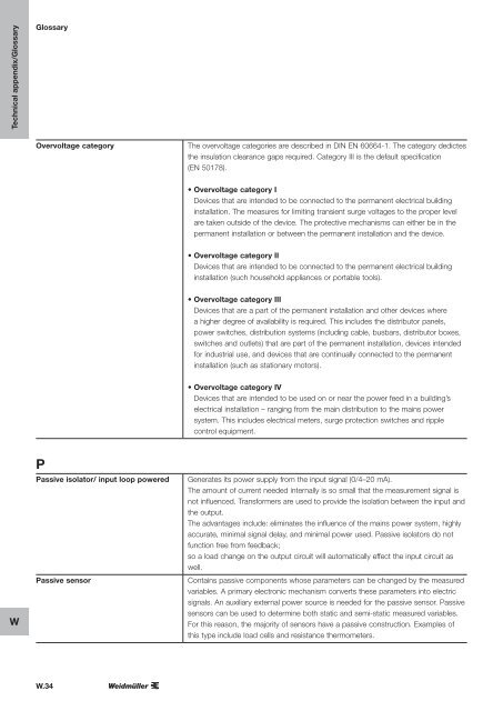
- Page 284 and 285: Glossary Technical appendix/Glossar
- Page 288 and 289: Glossary Technical appendix/Glossar
- Page 290 and 291: Glossary Technical appendix/Glossar
- Page 292 and 293: Glossary Technical appendix/Glossar
- Page 294 and 295: Contents Index Index Index Index Ty
- Page 296 and 297: Type Order No. Page Type Order No.
- Page 298 and 299: Order No. Type Page Order No. Type
- Page 300 and 301: Group companies Agency abroad Witho


