ÐаÑалог Weidmuller: Electronics - Analogue Signal Conditioning
ÐаÑалог Weidmuller: Electronics - Analogue Signal Conditioning
ÐаÑалог Weidmuller: Electronics - Analogue Signal Conditioning

You also want an ePaper? Increase the reach of your titles
YUMPU automatically turns print PDFs into web optimized ePapers that Google loves.
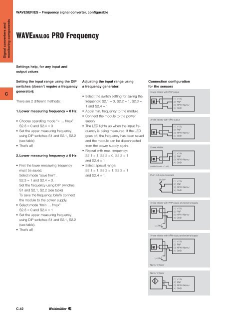
WAVESERIES – Frequency signal converter, configurable<br />
<strong>Signal</strong> converters and<br />
monitoring components<br />
WAVEanalog PRO Frequency<br />
Settings help, for any input and<br />
output values<br />
C<br />
Setting the input range using the DIP<br />
switches (doesn’t require a frequency<br />
generator):<br />
There are 2 different methods:<br />
1. Lower measuring frequency = 0 Hz<br />
• Choose operating mode “= … fmax”<br />
S2.3 = 0 and S2.4 = 0<br />
• Set the upper measuring frequency<br />
using DIP switches S1 and S2.1, S2.2<br />
(see table)<br />
• That’s all!<br />
2. Lower measuring frequency ≠ 0 Hz<br />
• First the lower measuring frequency<br />
must be saved.<br />
Select mode “save fmin”.<br />
S2.3 = 1 and S2.4 = 0.<br />
Set the frequency using DIP switches<br />
S1 and S2.1, S2.2 (see table)<br />
To save the frequency, briefly connect<br />
the module to the power supply.<br />
• Select mode “fmin … fmax”<br />
S2.3 = 0 and S2.4 = 1<br />
• Set the upper measuring frequency<br />
using DIP switches S1 and S2.1, S2.2<br />
(see table).<br />
• That’s all!<br />
Adjusting the input range using<br />
a frequency generator:<br />
• Select the switch setting for saving the<br />
frequency: S2.1 = 0, S2.2 = 1, S2.3 =<br />
1 and S2.4 = 1<br />
• Apply min. frequency to the module<br />
• Connect the module to the power<br />
supply<br />
• The LED lights up when the input frequency<br />
is being measured. If the LED<br />
goes off, the frequency has been saved<br />
and the module can be disconnected<br />
from the power supply again.<br />
• Repeat with max. frequency:<br />
S2.1 = 1, S2.2 = 0, S2.3 = 1<br />
and S2.4 = 1<br />
• Select special range:<br />
S2.1 = 1, S2.2 = 1, S2.3 = 1<br />
and S2.4 = 1<br />
3-wire<br />
3-wire<br />
initiator<br />
initiator<br />
with<br />
with<br />
PNP<br />
PNP<br />
output<br />
output<br />
(1)<br />
(1)<br />
+15V<br />
+15V<br />
3-wire initiator with PNP output<br />
(2)<br />
(2)<br />
PNP<br />
PNP<br />
(3)<br />
(3)<br />
NPN<br />
NPN<br />
/Namur<br />
/Namur<br />
(1)<br />
(4)<br />
(4) +15V<br />
GND<br />
GND<br />
(2) PNP<br />
(3) NPN /Namur<br />
(4) GND<br />
3-wire<br />
3-wire<br />
initiator<br />
initiator<br />
with<br />
with<br />
NPN<br />
NPN<br />
output<br />
output<br />
Connection configuration<br />
3-wire initiator with PNP output<br />
3-wire initiator with PNP output<br />
for the sensors<br />
3-wire initiator with PNP output<br />
(1) +15V<br />
3-wire initiator with PNP output (1) +15V<br />
(2) PNP<br />
(1) (2) +15V PNP<br />
(3) NPN /Namur<br />
(2)<br />
(1) (3) NPN PNP<br />
(4) +15V/Namur<br />
GND<br />
(3) NPN /Namur<br />
(2) (4) PNP GND<br />
(4) GND<br />
(3) NPN /Namur<br />
(4) GND<br />
3-wire initiator with NPN output<br />
3-wire initiator with NPN output<br />
3-wire initiator with NPN output<br />
(1) +15V<br />
3-wire initiator with NPN output (1) +15V<br />
(2) PNP<br />
(1) (2) +15V PNP<br />
(3) NPN /Namur<br />
(2)<br />
(1) (3) NPN PNP<br />
(4) +15V/Namur<br />
GND<br />
(3) NPN /Namur<br />
(2) (4) PNP GND<br />
(4) GND<br />
(3) NPN /Namur<br />
(4) GND<br />
2-wire initiator<br />
2-wire initiator<br />
2-wire initiator<br />
(1) +15V<br />
2-wire initiator<br />
(1) +15V<br />
(2) PNP<br />
(1) (2) +15V PNP<br />
(3) NPN /Namur<br />
(3) (2)<br />
(4) (1) NPN PNP<br />
GND +15V/Namur<br />
(3) (4) NPN<br />
(2) GND /Namur<br />
PNP<br />
(residual current < 1 mA)<br />
(residual current < 1 mA) (4) GND<br />
(3) NPN /Namur<br />
(residual current < 1 mA) (4) GND<br />
(residual current < 1 mA)<br />
Push pull output cascade<br />
Push pull output cascade<br />
Push pull U=24V output cascade<br />
U=24V (1) +15V<br />
Push pull output cascade<br />
(1) +15V<br />
U=24V (2) PNP<br />
(1) (2) +15V PNP<br />
(3) NPN /Namur<br />
U=24V (3) (2) PNP<br />
(4) (1) NPN<br />
GND +15V/Namur<br />
(3) (4) NPN /Namur<br />
(2) GND PNP<br />
(4) GND<br />
(3) NPN /Namur<br />
(4) GND<br />
3-wire<br />
3-wire<br />
initiator<br />
initiator<br />
with<br />
with<br />
PNP<br />
PNP<br />
output<br />
output<br />
and<br />
and<br />
external<br />
external<br />
supply<br />
supply<br />
(1)<br />
(1)<br />
+15V<br />
+15V<br />
3-wire initiator with PNP output (2)<br />
(2)<br />
PNP<br />
PNPand external supply<br />
(3)<br />
(3)<br />
NPN<br />
NPN /<br />
Namur<br />
Namur<br />
(1)<br />
(4)<br />
(4) +15V<br />
GND<br />
GND<br />
(2) PNP<br />
(3) NPN / Namur<br />
U=24V<br />
U=24V<br />
(4) GND<br />
3-wire<br />
3-wire U=24V initiator<br />
initiator<br />
with<br />
with<br />
NPN<br />
NPN<br />
output<br />
output<br />
and<br />
and<br />
external<br />
external<br />
supply<br />
supply<br />
3-wire initiator with P<br />
3-wire initiator with P<br />
3-wire initiator with P<br />
3-wire initiator with P<br />
U=24V<br />
U=24V<br />
U=24V<br />
3-wire U=24V initiator with N<br />
3-wire initiator with N<br />
3-wire initiator with N<br />
3-wire initiator with N<br />
U=24V<br />
U=24V<br />
U=24V<br />
Namur initiator<br />
Namur U=24V initiator<br />
Namur initiator<br />
Namur initiator<br />
N+<br />
N+<br />
N-<br />
N- N+<br />
N-<br />
N+<br />
N-<br />
(1)<br />
(1)<br />
+15V<br />
+15V<br />
3-wire initiator with NPN output<br />
(2)<br />
(2)<br />
PNP<br />
PNP<br />
(3)<br />
(3)<br />
NPN<br />
NPN<br />
/Namur<br />
/Namur<br />
(1)<br />
(4)<br />
(4) +15V<br />
GND<br />
GND<br />
(2) PNP<br />
(3) NPN /Namur<br />
(4) GND<br />
(1)<br />
(1)<br />
+15V<br />
+15V<br />
3-wire initiator with NPN output (2)<br />
(2)<br />
PNP<br />
PNPand external supply<br />
(3)<br />
(3)<br />
NPN<br />
NPN /<br />
Namur<br />
Namur<br />
(4)<br />
(4) (1) +15V<br />
GND<br />
GND<br />
(2) PNP<br />
(3) NPN / Namur<br />
U=24V<br />
U=24V<br />
(4) GND<br />
2-wire<br />
2-wire<br />
initiator<br />
initiator<br />
2-wire initiator<br />
(residual current < 1 mA)<br />
(residual current mA)<br />
(1)<br />
(1)<br />
+15V<br />
+15V<br />
(2)<br />
(2)<br />
PNP<br />
PNP<br />
(3)<br />
(3)<br />
NPN<br />
NPN<br />
/Namur<br />
/Namur<br />
(4)<br />
(4) (1)<br />
GND<br />
GND +15V<br />
(2) PNP<br />
(3) NPN /Namur<br />
(4) GND<br />
Namur<br />
Namur<br />
initiator<br />
initiator<br />
U=24V<br />
Namur initiator N+<br />
N+<br />
N-<br />
N-<br />
N+<br />
N-<br />
(1)<br />
(1)<br />
+15V<br />
+15V<br />
(2)<br />
(2)<br />
PNP<br />
PNP<br />
(3)<br />
(3)<br />
NPN<br />
NPN /<br />
Namur<br />
Namur<br />
(4)<br />
(4) (1) +15V<br />
GND<br />
GND<br />
(2) PNP<br />
(3) NPN / Namur<br />
(4) GND<br />
C.42<br />
(residual current < 1 mA)<br />
Push<br />
Push<br />
pull<br />
pull<br />
output<br />
output<br />
cascade<br />
cascade<br />
U=24V<br />
U=24V<br />
(1)<br />
(1)<br />
+15V<br />
+15V<br />
Push pull output cascade(2) PNP<br />
PNP<br />
U=24V (3)<br />
(3)<br />
NPN<br />
NPN<br />
/Namur<br />
/Namur<br />
(4)<br />
(4) (1)<br />
GND<br />
GND +15V<br />
(2) PNP<br />
(3) NPN /Namur<br />
(4) GND