ÐаÑалог Weidmuller: Electronics - Analogue Signal Conditioning
ÐаÑалог Weidmuller: Electronics - Analogue Signal Conditioning
ÐаÑалог Weidmuller: Electronics - Analogue Signal Conditioning

Create successful ePaper yourself
Turn your PDF publications into a flip-book with our unique Google optimized e-Paper software.
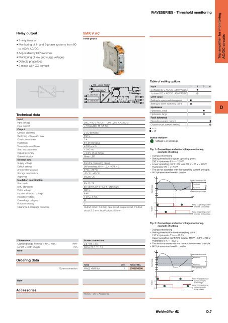
Relay output<br />
• 2-way isolation<br />
• Monitoring of 1- and 3-phase systems from 80<br />
to 400 V AC/DC<br />
• Adjustable by DIP switches<br />
• Monitoring of low and surge voltages<br />
• Detects phase loss<br />
• 2 relays with CO contact<br />
VMR V AC<br />
Three-phase<br />
WAVESERIES - Threshold monitoring<br />
Trip amplifier for monitoring<br />
AC/DC circuits<br />
Table of setting options<br />
Technical data<br />
Uac<br />
Input<br />
Input voltage<br />
Input current<br />
Output<br />
Contact assembly<br />
Switching voltage AC, max.<br />
Continuous current<br />
Hysteresis<br />
Temperature coefficient<br />
Step response time<br />
Repeat accuracy<br />
Status indicator<br />
General data<br />
Supply voltage<br />
Default setting<br />
Ambient temperature<br />
Storage temperature<br />
Approvals<br />
Insulation coordination<br />
Standards<br />
EMC standards<br />
Rated voltage<br />
Impulse withstand voltage<br />
Insulation voltage<br />
Overvoltage category<br />
Pollution severity<br />
Clearance & creepage distances<br />
4<br />
5<br />
6<br />
1<br />
200…400 V AC/DC<br />
2<br />
80…250 V AC/DC L1<br />
3<br />
80…250V AC/DC L2<br />
N<br />
80…250V AC/DC L3<br />
11<br />
12<br />
7<br />
8<br />
14 9<br />
21<br />
10<br />
L1 L2 L3 22 11<br />
24 12<br />
200…400 V AC/DC 1~, 80…250 V AC/DC 3~<br />
< 10 mA DC; 15 mA AC<br />
2 CO contacts<br />
250 V<br />
3 A<br />
5% of final value<br />
≤ 300 ppm/K<br />
< 300 ms<br />
< 0.3% of set range<br />
Green LED<br />
from the measuring circuit<br />
DIP switches: ON = 1,2,4 / OFF = 3<br />
0 °C...+50 °C<br />
-25 °C...+85 °C<br />
cULus; CE<br />
EN 50178<br />
EN 55011, EN 61000-6, EN 61326<br />
600 V<br />
6 kV<br />
4 kV eff<br />
/ 1 min.<br />
III<br />
2<br />
Output circuit: 1.8 mm; input circuit, output circuit 1/output<br />
circuit 2: 3 mm; input/output: 5.5 mm<br />
Input<br />
1 2 3 4<br />
3 phases 80 V AC/DC...250 V AC/DC <br />
1 phase 200 V AC/DC...400 V AC/DC <br />
Limit value<br />
Setting to upper switching point <br />
Setting to lower switching point <br />
Hysteresis<br />
Hysteresis, small<br />
<br />
Hysteresis, large<br />
<br />
Fault tolerance<br />
Operating current method<br />
<br />
Closed-circuit current method<br />
= on<br />
= off<br />
Status indicator<br />
Voltage is in set range<br />
Fig. 1: Overvoltage and undervoltage monitoring,<br />
example of setting<br />
– 3-phase monitoring<br />
– Setting threshold to upper operating point:<br />
230 V Hysteresis 5% = -12,5 V<br />
– Lower operating point 10% less 230 V - 25 V = 205 V<br />
Hyster esis 5% = + 12 ,5 V<br />
– The device operates with the operating current principle.<br />
– All 3 phases monitored in parallel<br />
Input range<br />
Output<br />
U<br />
1<br />
0<br />
0<br />
1<br />
0<br />
Upper operating point<br />
Time<br />
Hysteresis<br />
Hysteresis<br />
10 %<br />
Lower operating point<br />
Relay 1/Operating current<br />
principle, Overvoltage<br />
Relay 2/Operating current<br />
principle, Undervoltage<br />
D<br />
Fig. 2: Overvoltage and undervoltage monitoring,<br />
example of setting<br />
Dimensions<br />
Clamping range (nominal / min. / max.)<br />
Length x width x height<br />
Note<br />
mm²<br />
mm<br />
Screw connection<br />
2.5 / 0.5 / 2.5<br />
96.5 / 22.5 / 112.5<br />
– 3-phase monitoring<br />
– Setting threshold to lower operating point:<br />
150 V Hysteresis 5% = +12,5 V<br />
– Upper operating point 20% greater 150 V + 50 V = 200 V<br />
Hyster esis 5 % = –1 2, 5 V<br />
– The device operates with the closed-circuit current principle.<br />
– All 3 phases monitored in parallel<br />
U<br />
Upper operating point<br />
Ordering data<br />
Screw connection<br />
Type Qty. Order No.<br />
WAS2 VMR 3ph 1 8705630000<br />
Input range<br />
0<br />
Hysteresis<br />
20%<br />
Hysteresis<br />
Lower operating point<br />
Time<br />
Note<br />
Accessories<br />
Markers – refer to Accessories.<br />
Output<br />
1<br />
0<br />
1<br />
0<br />
Relay 1 /Closed-circuit<br />
current principle,<br />
Overvoltage<br />
Relay 2 /Closed-circuit<br />
current principle,<br />
Undervoltage<br />
D.7