ÐаÑалог Weidmuller: Electronics - Analogue Signal Conditioning
ÐаÑалог Weidmuller: Electronics - Analogue Signal Conditioning
ÐаÑалог Weidmuller: Electronics - Analogue Signal Conditioning

You also want an ePaper? Increase the reach of your titles
YUMPU automatically turns print PDFs into web optimized ePapers that Google loves.
Technical appendix/Glossary<br />
Technical data<br />
The secondary winding supplies the measuring electronics<br />
with a proportional current signal. Because of power loss this<br />
method of measuring current is limited to smaller currents up<br />
to 5 A. These converters react sensitively to peak loads and<br />
therefore have to be fused on the primary winding side.<br />
The microprocessor compares the value measured with the<br />
characteristic curve for the thermocouple in its memory and<br />
calculates the corresponding value on the “ideal characteristic<br />
curve”. At the output, it supplies the latter to an amplifier,<br />
which produces the analogue value in linear form. The output<br />
stage converts this into a standardised value or into a<br />
switching output with a switching threshold.<br />
The linearisation of PT100-elements can be undertaken via<br />
simple amplifier stages. The first stage corrects the peak val<br />
ue of the graph of the measurements. The deviation at the<br />
end of the graph resulting from this is corrected by a second<br />
stage. The under- and over-shooting generated in this way is<br />
very slight and is covered by the tolerance for the module.<br />
Measuring Current Using A Hall-type Sensor<br />
• Hall-type sensor principle<br />
Hall-type sensors also measure the magnetic flux B and<br />
supply a proportional voltage at the measured output, which<br />
is then reconditioned to form a standard signal by an amplifier<br />
circuit.<br />
• Components with Hall-type sensors are ideally suited to<br />
measuring higher currents, as any possible high residual<br />
currents from motors or peak loads cannot damage the<br />
component. Additionally, they are also ideal for measuring<br />
direct and alternating currents of various curve shapes.<br />
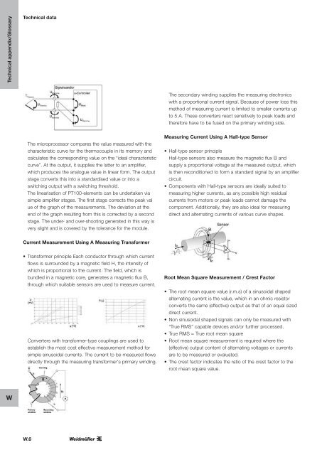
Current Measurement Using A Measuring Transformer<br />
• Transformer principle Each conductor through which current<br />
flows is surrounded by a magnetic field H, the intensity of<br />
which is proportional to the current. The field, which is<br />
bundled in a magnetic core, generates a magnetic flux B,<br />
through which suitable sensors are used to measure current.<br />
Converters with transformer-type couplings are used to<br />
establish the most cost effective measurement method for<br />
simple sinusoidal currents. The current to be measured flows<br />
directly through the measuring transformer‘s primary winding.<br />
Root Mean Square Measurement / Crest Factor<br />
• The root mean square value (r.m.s) of a sinusoidal shaped<br />
alternating current is the value, which in an ohmic resistor<br />
converts the same (effective) output as that of an equal sized<br />
direct current.<br />
• Non sinusoidal shaped signals can only be measured with<br />
“True RMS” capable devices and/or further processed.<br />
• True RMS = True root mean square<br />
• Root mean square measurement is required where the<br />
(effective) output content of alternating voltages or currents<br />
are to be measured or evaluated.<br />
• The crest factor indicates the ratio of the crest factor to the<br />
root mean square value.<br />
W<br />
W.6