ÐаÑалог Weidmuller: Electronics - Analogue Signal Conditioning
ÐаÑалог Weidmuller: Electronics - Analogue Signal Conditioning
ÐаÑалог Weidmuller: Electronics - Analogue Signal Conditioning

Create successful ePaper yourself
Turn your PDF publications into a flip-book with our unique Google optimized e-Paper software.
Technical data<br />
Technical appendix/Glossary<br />
Load / Load Resistor<br />
• The load is a load resistor on the output side of a measuring<br />
transducer or isolating amplifier.<br />
The load is usually less than 500 Ω at the current outputs.<br />
Voltage outputs are normally under a load greater than 1 KΩ.<br />
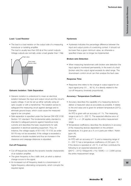
Peak value<br />
Root mean<br />
square value<br />
Hysteresis<br />
• Hysteresis indicates the percentage difference between the<br />
input and output points of a switching contact. It should not<br />
be lower than a given minimum value, as otherwise a<br />
specified chase can no longer be implemented.<br />
Broken-wire Detection<br />
• When measuring transformers with broken wire detection the<br />
input signal is monitored permanently. In the event of a fault<br />
(broken wire) the output signal exceeds its rated range. The<br />
downstream control circuit can then analyse the fault case.<br />
Response Time<br />
Galvanic Isolation / Safe Separation<br />
• Response time refers to the change in output signal for an<br />
input signal jump (10 … 90 %). It is directly related to the<br />
cut-off frequency (inversely proportional).<br />
• Galvanic isolation is understood to mean an electrical<br />
isolation between the input and output circuit and the circuit‘s<br />
supply voltage. It can be set up either optically using an<br />
opto coupler or with a transformer. The isolation serves to<br />
safeguard the measuring circuit against damage and to<br />
eliminate ground loops, which could cause the measured<br />
signal to be corrupted.<br />
• Safe separation is specified under the German DIN VDE 0106<br />
Section 101 standard. This fundamental safety standard is<br />
intended to safeguard persons against hazardous body<br />
currents and describes the basic requirements for safe<br />
separation in electrical operating equipment. Thus, for<br />
instance, the voltage supply of 50 V AC/ 75 V DC as under<br />
50178 may not be exceeded. If this voltage is exceeded a<br />
reinforced or double insulated and thus an increase in the<br />
clearance and creepage distances is stipulated.<br />
Cut-off Frequency<br />
• Cut-off frequencies indicate the dynamic transfer characteristic<br />
of an isolation amplifier.<br />
• The given frequency is the (-3dB-) limit, at which a distinct<br />
change occurs to the signal.<br />
• An increased cut-off frequency leads to a transmission of<br />
higher-frequency alternating components, which corrupts the<br />
required signal.<br />
Accuracy / Temperature Coefficient<br />
• Accuracy describes the capability of a measuring device to<br />
deliver a measured value as accurately as possible. It relates<br />
to the end value and is given for ambient temperature (23°C).<br />
Example:<br />
An RTD is given with an accuracy of 1 %. The measuring<br />
range is set to 0 – 200 °C. The expected effective error of:<br />
200*1 % = +/– 2K applies across the entire measurement<br />
range.<br />
• Temperature coefficiency describes the deviations in accuracy<br />
of the measuring devices dependent on the ambient<br />
temperature. It is given as a % or in parts per million / Kelvin<br />
(ppm /K).<br />
Example:<br />
An RTD with an accuracy of 1 % and a measuring range of<br />
0 – 200 °C has a temperature coefficiency of 250 ppm / K.<br />
If the device is operated at +40 °C, it will then contribute the<br />
following to an expected absolute error:<br />
(([40°C – 23°C] *250ppm/K) +1%) *200K) = +/– 2,85K across<br />
the entire measurement range.<br />
W<br />
W.7